


Visualizing software behavior is a critical step in the design phase. UML Sequence Diagrams provide a structured way to represent interactions between objects over time. They are not merely drawings; they are logical blueprints that define how data moves, how systems react, and where failures might occur. This guide explores ten practical scenarios to illustrate these interactions clearly.
Understanding the Core Components 🧩
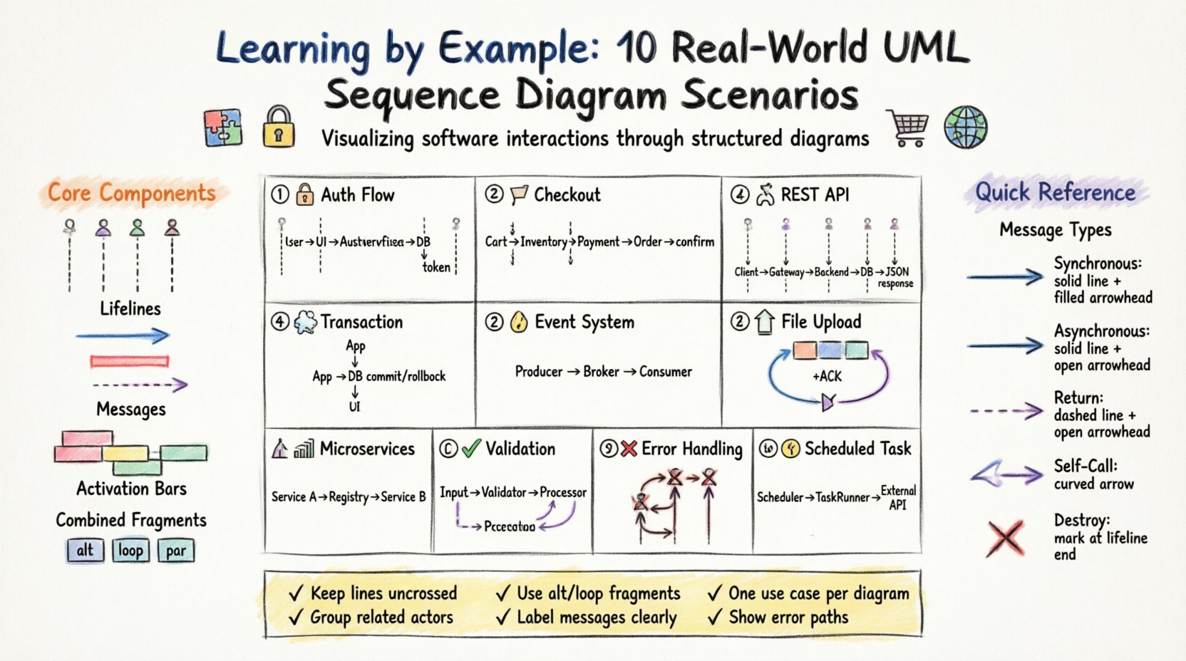
Before diving into specific examples, it is essential to establish a shared vocabulary. A sequence diagram relies on a few fundamental elements to convey meaning effectively.
- Lifelines: Vertical dashed lines representing participants (users, systems, databases). They show existence over time.
- Messages: Arrows indicating communication. They can be synchronous (waiting for a reply) or asynchronous (fire and forget).
- Activation Bars: Rectangles on lifelines showing when an object is performing an action.
- Combined Fragments: Boxes denoting loops, options, or parallel processing.
These elements combine to form a narrative. The vertical axis represents time moving downwards. The horizontal axis represents the distance between logical components. Keeping this spatial relationship clear ensures the diagram remains readable.
Scenario 1: User Authentication Flow 🔐
This is a foundational pattern found in almost every application. It demonstrates how credentials are validated and sessions are created.
- Actors: User Interface, Authentication Service, Database.
- Flow:
- User submits credentials via the interface.
- Interface forwards data to the Authentication Service.
- Service queries the Database for user records.
- Database returns the stored hash.
- Service compares hashes.
- If valid, a token is generated and returned to the User Interface.
- If invalid, an error message is sent.
This scenario highlights the importance of separation of concerns. The interface does not query the database directly; the service layer manages the logic.
Scenario 2: Shopping Cart Checkout 🛒
Complex transactions require coordination between multiple systems. This scenario shows how inventory, billing, and orders interact.
- Actors: Customer, Cart Service, Inventory Service, Payment Gateway, Order Service.
- Flow:
- Customer requests to checkout.
- Cart Service validates item availability with Inventory Service.
- Payment Gateway processes the transaction.
- Upon success, Order Service creates the order record.
- Inventory Service updates stock levels.
- Confirmation is sent to the Customer.
Note the dependency on the Payment Gateway. If this step fails, the system must trigger a rollback to restore inventory levels. Sequence diagrams help visualize these conditional paths.
Scenario 3: REST API Request and Response 🌐
Modern systems often communicate via standardized protocols. This example focuses on a standard GET request to retrieve data.
- Actors: Client, API Gateway, Backend Service, Database.
- Flow:
- Client sends HTTP GET request with specific parameters.
- API Gateway validates the request token.
- Request is routed to the Backend Service.
- Backend Service constructs a query.
- Database returns the result set.
- Backend Service formats the data into JSON.
- API Gateway sends the HTTP 200 response.
This pattern emphasizes statelessness. The API Gateway does not store session data between requests; it routes based on the current token.
Scenario 4: Database Transaction Management 💾
Data integrity relies on transactions. This scenario illustrates the Commit and Rollback mechanisms.
- Actors: Application, Database Management System.
- Flow:
- Application begins a transaction block.
- Statement A executes (e.g., update account).
- Statement B executes (e.g., update ledger).
- Application requests a commit.
- Database confirms the commit.
- Or, if an error occurs, Application requests a rollback.
- Database discards changes.
Sequence diagrams clarify the timing of the commit. It is not automatic; it is an explicit message sent from the application.
Scenario 5: Event Notification System 🔔
Systems often need to inform other parts of the architecture without direct coupling. This uses an asynchronous approach.
- Actors: Event Producer, Message Broker, Event Consumer.
- Flow:
- Producer detects a state change.
- Producer publishes an event to the Broker.
- Producer does not wait for confirmation.
- Broker stores the event.
- Consumer subscribes to the topic.
- Consumer retrieves and processes the event.
- Consumer sends an acknowledgement to the Broker.
This decouples the producer from the consumer. If the consumer is down, the Broker holds the message. This flow is critical for resilient architectures.
Scenario 6: File Upload Process 📤
Handling large data requires chunking and validation. This scenario covers the lifecycle of a file transfer.
- Actors: User, Upload Service, Storage System.
- Flow:
- User initiates upload of a large file.
- Service validates file size limits.
- Service generates a unique ID for the session.
- User sends chunks sequentially.
- Service acknowledges each chunk receipt.
- User signals completion.
- Service assembles chunks in Storage System.
- Service runs a virus scan.
- Service confirms availability to the User.
Notice the multiple round trips for chunk acknowledgment. This prevents data loss if a network interruption occurs.
Scenario 7: Microservice Communication 🏗️
In distributed systems, services talk to each other directly. This example shows service discovery and routing.
- Actors: Service A, Service B, Service Registry.
- Flow:
- Service A needs data from Service B.
- Service A queries Service Registry for Service B’s address.
- Registry returns the IP and port.
- Service A sends the request directly to Service B.
- Service B processes the logic.
- Service B returns the response.
- Service A caches the response for future use.
This pattern reduces the load on the registry over time. Once the address is known, direct communication is more efficient.
Scenario 8: Data Validation Flow ✅
Input validation prevents bad data from entering the system. This scenario occurs before the main business logic.
- Actors: Input Handler, Validator, Main Processor.
- Flow:
- Input Handler receives raw data.
- Handler passes data to Validator.
- Validator checks format (e.g., email regex).
- Validator checks existence (e.g., foreign key).
- Validator returns pass/fail status.
- If pass, data goes to Main Processor.
- If fail, error is returned to Input Handler.
Separating validation logic makes the Main Processor cleaner. It assumes data is correct and focuses on processing.
Scenario 9: Error Handling and Exception Propagation ❌
Systems fail. This diagram maps how errors travel up the stack.
- Actors: Client, Controller, Service, Repository.
- Flow:
- Client requests data.
- Controller calls Service.
- Service calls Repository.
- Repository throws a database exception.
- Service catches the exception.
- Service logs the error details.
- Service throws a user-friendly exception.
- Controller catches the exception.
- Controller returns an HTTP 500 error.
This ensures sensitive database errors do not leak to the client while ensuring the user knows something went wrong.
Scenario 10: Scheduled Task Execution ⏰
Background jobs run without user interaction. This scenario covers the trigger and execution.
- Actors: Scheduler, Task Runner, External API.
- Flow:
- Scheduler triggers at a specific time.
- Scheduler wakes the Task Runner.
- Task Runner checks for pending jobs.
- Task Runner connects to External API.
- External API processes the batch.
- External API returns status.
- Task Runner updates job logs.
- Task Runner goes back to sleep.
Sequence diagrams for scheduled tasks often include a time indicator to show the gap between the trigger and the execution.
Message Types and Behavior Table 📋
Understanding the arrow types is crucial for accurate diagramming. The following table outlines common message types and their behaviors.
| Message Type | Arrow Style | Behavior | Use Case |
|---|---|---|---|
| Synchronous | Solid Line + Filled Arrow | Caller waits for response | API Calls, Function Calls |
| Asynchronous | Solid Line + Open Arrow | Caller does not wait | Notifications, Fire-and-forget |
| Return | Dashed Line + Open Arrow | Response to synchronous call | Data Return, Status Confirmation |
| Self-Call | Curved Arrow | Object calls itself | Recursive Logic, Internal Methods |
| Destroy | X Mark | Lifeline ends | Session Termination, Object Deletion |
Best Practices for Design 🛠️
Creating a readable diagram requires discipline. Adhering to specific guidelines improves clarity for all stakeholders.
- Keep it Flat: Avoid crossing lines. If lines cross, the diagram becomes hard to follow.
- Group Related Actors: Place actors that interact frequently close to each other horizontally.
- Use Combined Fragments: Use
altfor alternatives andloopfor iterations instead of drawing every single step. - Label Messages Clearly: Include the method name or action verb on the arrow.
- Limit Scope: Focus on one use case per diagram. Do not mix login flows with checkout flows.
- Time Consistency: Ensure the vertical spacing reflects relative time duration where possible.
Common Pitfalls to Avoid ⚠️
Even experienced designers make mistakes. Being aware of these common errors saves time during review.
- Ignoring Error Paths: Only showing the happy path makes the system look fragile.
- Too Many Lifelines: If a diagram has more than 10 vertical lines, it is likely too complex and should be split.
- Missing Return Messages: For synchronous calls, the return path is implied but should be shown for clarity in complex flows.
- Vague Actors: Avoid generic labels like “System” or “User.” Use specific names like “Payment Gateway” or “Frontend Client.”
- Ignoring State: A sequence diagram does not show state changes well. Supplement it with a State Diagram if needed.
Final Considerations 🎯
Sequence diagrams are a communication tool, not just a technical artifact. They bridge the gap between business requirements and code implementation. By studying these ten real-world scenarios, you gain insight into how data flows through complex systems.
Focus on clarity and precision. A well-drawn diagram reduces ambiguity during development. It allows teams to identify bottlenecks, race conditions, and logical gaps before writing a single line of code. Use these examples as a foundation for your own architectural designs.
Remember that tools change, but the logic remains constant. Whether you are designing a monolith or a distributed system, the principles of interaction and timing do not change. Apply these patterns consistently to maintain high standards in your documentation.