


Agile development prioritizes flexibility, collaboration, and iterative progress. Within this dynamic environment, documentation often faces scrutiny. However, clear communication remains a cornerstone of successful software engineering. One specific artifact stands out for its ability to clarify temporal interactions between system components: the UML Sequence Diagram. When integrated thoughtfully, these diagrams serve as a bridge between abstract requirements and concrete implementation. They provide a visual language that translates complex logic into an understandable flow.
This guide explores the function of UML Sequence Diagrams within Agile methodologies. We will examine how they support sprint planning, reduce ambiguity, and maintain architectural integrity without slowing down delivery. The focus remains on the utility of these diagrams as a communication tool rather than a rigid specification.
Understanding UML Sequence Diagrams 📊
Before integrating these diagrams into a workflow, it is essential to understand their structure and purpose. A UML Sequence Diagram is a type of interaction diagram. It shows how objects interact with one another over time. Unlike a class diagram, which focuses on static structure, a sequence diagram focuses on dynamic behavior.
Key elements include:
- Lifelines: Vertical dashed lines representing objects or participants.
- Messages: Arrows indicating calls, signals, or returns between lifelines.
- Activation Bars: Rectangles on lifelines showing when an object is actively processing a request.
- Combined Fragments: Boxes indicating control flow logic like loops or conditionals.
These components allow teams to visualize the exact order of operations. This clarity is vital when multiple developers are working on interconnected parts of a system. It prevents assumptions about how one service triggers another.
The Agile Landscape ⚡
Agile methodologies emphasize working software over comprehensive documentation. This principle often leads to a misconception that diagrams are obsolete. In reality, the need for understanding system behavior has not decreased; it has merely shifted. The challenge lies in creating documentation that keeps pace with rapid iterations.
Traditional documentation often becomes outdated quickly. Agile requires documentation that is lightweight yet effective. Sequence diagrams fit this requirement because they can be created quickly during refinement sessions and updated alongside code changes. They serve as a shared mental model for the team.
Why Documentation Matters in Sprints
During a sprint, the team focuses on delivering value. However, without clear interaction maps, technical debt can accumulate. Common issues include:
- Integration Failures: APIs do not match expectations.
- Logic Gaps: Edge cases are missed during coding.
- Onboarding Friction: New team members struggle to understand the flow.
Sequence diagrams mitigate these risks by providing a snapshot of the intended flow before code is written. This does not require extensive up-front design. Instead, it supports Just-In-Time modeling.
Bridging Requirements and Implementation 🤝
User stories describe functionality from a user perspective. They often lack technical detail. A sequence diagram translates a user story into technical steps. This translation helps developers identify dependencies and data flows early.
Consider a scenario where a user places an order. The user story might state: “As a user, I want to place an order so that I can purchase items.” The sequence diagram reveals:
- The frontend sends a request to the API gateway.
- The gateway validates the token.
- The order service checks inventory.
- The payment service processes the transaction.
- The notification service sends a confirmation email.
This breakdown exposes hidden complexity. It ensures that all necessary services are accounted for before development begins. It also helps the team identify who owns which part of the interaction.
Benefits of Integration 📈
Using sequence diagrams in Agile offers specific advantages. These benefits extend beyond mere documentation. They influence team dynamics and code quality.
| Benefit | Description |
|---|---|
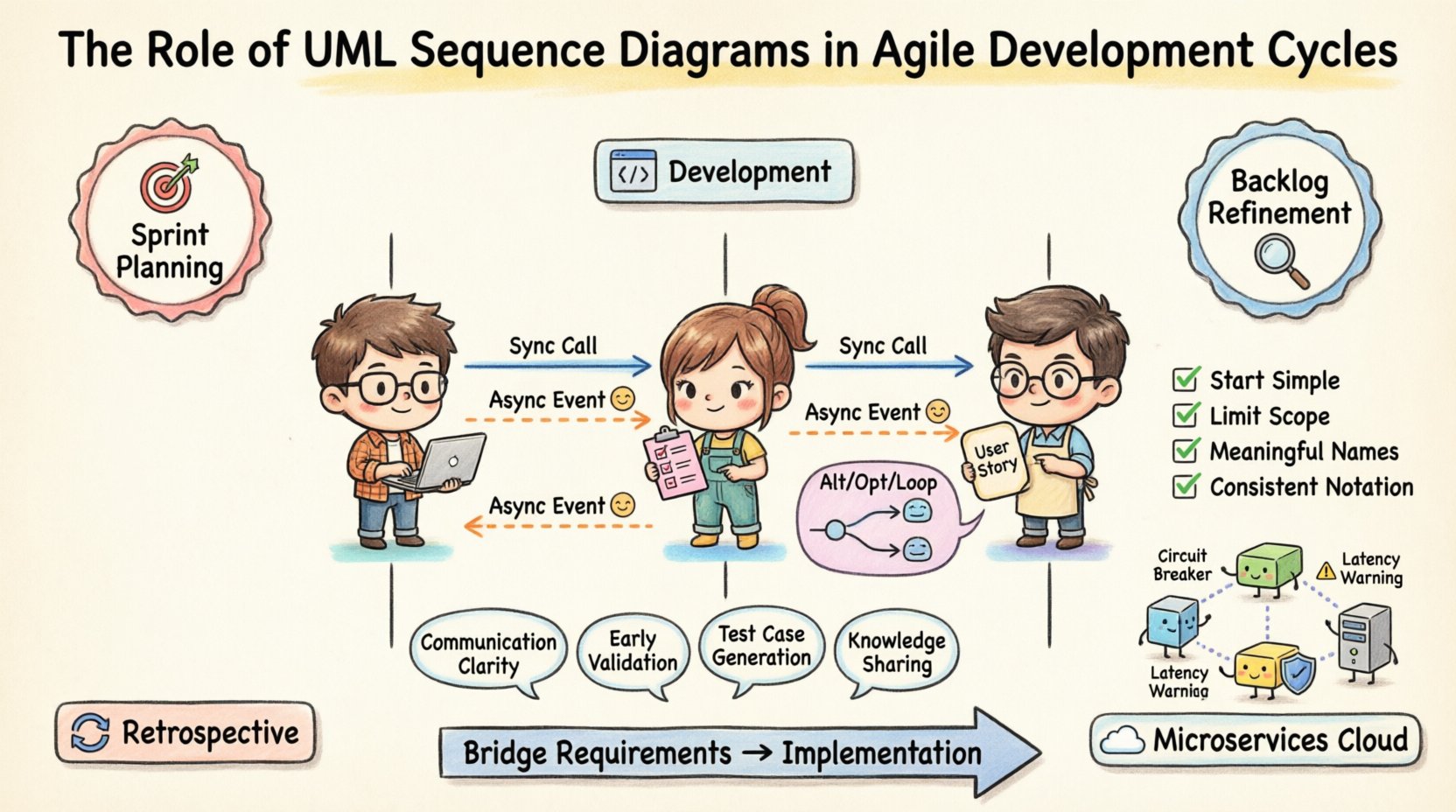
| Communication Clarity | Visualizes data flow, reducing verbal misunderstandings. |
| Early Validation | Identifies architectural flaws before code is committed. |
| Test Case Generation | Provides a clear basis for creating integration tests. |
| Knowledge Sharing | Acts as a reference for new team members. |
Technical Anatomy and Detail 🛠️
To be effective, a sequence diagram must use standard notation correctly. Misusing symbols can lead to confusion. Here is a breakdown of specific message types and how they function.
Message Types
- Synchronous Messages: The caller waits for the receiver to complete the task. This is common when data must be returned immediately.
- Asynchronous Messages: The caller sends the request and continues without waiting. This is typical for fire-and-forget events.
- Return Messages: Indicates data flowing back from the receiver to the caller.
Combined Fragments
Real-world logic rarely follows a straight line. Combined fragments allow the diagram to represent complex control structures.
- Alt (Alternative): Represents if/else logic. Shows different paths based on conditions.
- Opt (Optional): Indicates an optional interaction that may or may not occur.
- Loop: Shows repetitive actions, such as iterating through a list.
- Break: Indicates an early exit from a loop or process.
Using these fragments accurately prevents the diagram from becoming a linear list that fails to capture edge cases. It forces the team to consider what happens when things go wrong.
Implementing in Sprint Cycles 🗓️
Timing is critical. Drawing diagrams at the wrong time can waste effort. The best practice is to align diagramming with specific Agile ceremonies.
Sprint Planning
During planning, the team selects stories for the upcoming sprint. Sequence diagrams help estimate effort. If a story requires interactions with five different external systems, the diagram highlights the complexity. This leads to more accurate velocity predictions.
Backlog Refinement
Refinement sessions are ideal for creating drafts. The goal is not perfection but clarity. Teams can sketch diagrams on whiteboards or digital canvases. This facilitates discussion about potential bottlenecks. Questions like “What happens if the payment service is down?” can be answered by drawing a return message or an error path.
Development Phase
Developers use the diagram as a reference. It acts as a contract for the interface. If the code deviates from the diagram, the developer knows to update the diagram. This keeps the artifact alive and relevant.
Retrospectives
Retrospectives often reveal gaps in understanding. A sequence diagram can serve as evidence of what was planned versus what was built. If the actual flow differs significantly, the diagram helps identify where the communication breakdown occurred.
Common Challenges and Pitfalls ⚠️
While beneficial, sequence diagrams can become liabilities if mismanaged. Teams must avoid common traps that reduce their value.
- Over-Engineering: Creating diagrams for every trivial interaction adds noise. Focus on complex flows that involve multiple systems.
- Stale Artifacts: A diagram that is not updated is worse than no diagram. It gives false confidence.
- Too Much Detail: Do not show every variable passing. Show the high-level logic and data exchange points.
- Isolation: Do not create diagrams in a vacuum. Review them with the team to ensure alignment.
Maintenance and Evolution 🌱
Software evolves. Features are added, and logic changes. The diagram must evolve with it. In a version-controlled environment, diagrams can be treated like code. This allows for review processes and history tracking.
Text-based diagramming tools are often preferred in this context. They allow diagrams to be stored alongside source code. This ensures that the diagram is reviewed during pull requests. It prevents the documentation from drifting away from the implementation.
Automation is another avenue. Some tools can generate sequence diagrams from code analysis. While this reduces manual effort, it often lacks the semantic clarity of human-created diagrams. A hybrid approach is usually best: use code for baseline structure and manual editing for business logic.
Team Collaboration and Culture 🤝
Diagrams are not just technical artifacts; they are social tools. They facilitate conversation between developers, testers, and product owners.
- Developers: Use them to understand dependencies.
- Testers: Use them to design test scenarios.
- Product Owners: Use them to verify that the logic matches the requirement.
When everyone understands the diagram, the team moves faster. Disputes about who is responsible for a specific step can be resolved by pointing to the interaction flow. This reduces friction and speeds up decision-making.
Visualizing System Interactions 🖼️
Complex systems often involve microservices. In this architecture, the sequence diagram is indispensable. It maps the distributed nature of the system. It shows how a request travels across network boundaries.
Key considerations for microservices include:
- Latency: Show where network calls occur to highlight potential delays.
- Circuit Breakers: Indicate where failure handling occurs.
- Idempotency: Mark requests that must be safe to retry.
Without a visual map, debugging distributed systems becomes a guessing game. A sequence diagram provides the roadmap for tracing requests through the infrastructure.
Best Practices for Clarity ✨
To maximize utility, follow these guidelines when creating diagrams.
- Start Simple: Begin with the happy path. Add error handling later.
- Limit Scope: Do not try to show the entire system in one diagram. Break it down by feature or service.
- Use Meaningful Names: Label lifelines with specific service names, not generic terms like “Object A”.
- Consistent Notation: Agree on standards for the team. Ensure everyone uses the same arrow types and symbols.
- Keep it Readable: Avoid crossing lines where possible. Use swimlanes to group related interactions.
Conclusion and Next Steps 🚀
Integrating UML Sequence Diagrams into Agile cycles requires discipline but yields significant rewards. They transform abstract ideas into concrete plans. They reduce the risk of integration errors and improve team alignment.
The goal is not to create a perfect document. The goal is to create a living reference that aids understanding. By focusing on high-value interactions and maintaining the diagrams alongside the code, teams can enjoy the benefits of clear architecture without sacrificing agility.
Start small. Pick one complex user story for the next sprint. Draw the sequence diagram together. Review it during planning. Update it as you build. Over time, this practice will become a natural part of your workflow, strengthening the foundation of your development process.