


Understanding the architecture of a software system requires more than just listing classes and their relationships. While class diagrams describe the static blueprint of data and methods, they often fail to reveal how objects are physically or logically connected within a composite unit. This is where the Composite Structure Diagram becomes essential. For students diving into software engineering, mastering the internal structure of systems is a critical step toward professional competence. This guide provides a deep dive into the mechanics, usage, and nuances of the Composite Structure Diagram, bridging the gap between academic theory and real-world design.
🔍 What Is a Composite Structure Diagram?
A Composite Structure Diagram is a specialized type of diagram within the Unified Modeling Language (UML). It focuses on the internal structure of a classifier, such as a class or component. Unlike a class diagram, which shows the entire system’s static relationships, this diagram zooms in on a single unit to show how it is composed of smaller parts and how those parts interact.
Think of it as an x-ray for software architecture. Instead of seeing the outer shell of a class, you see the gears, wires, and modules inside. It reveals the following key aspects:
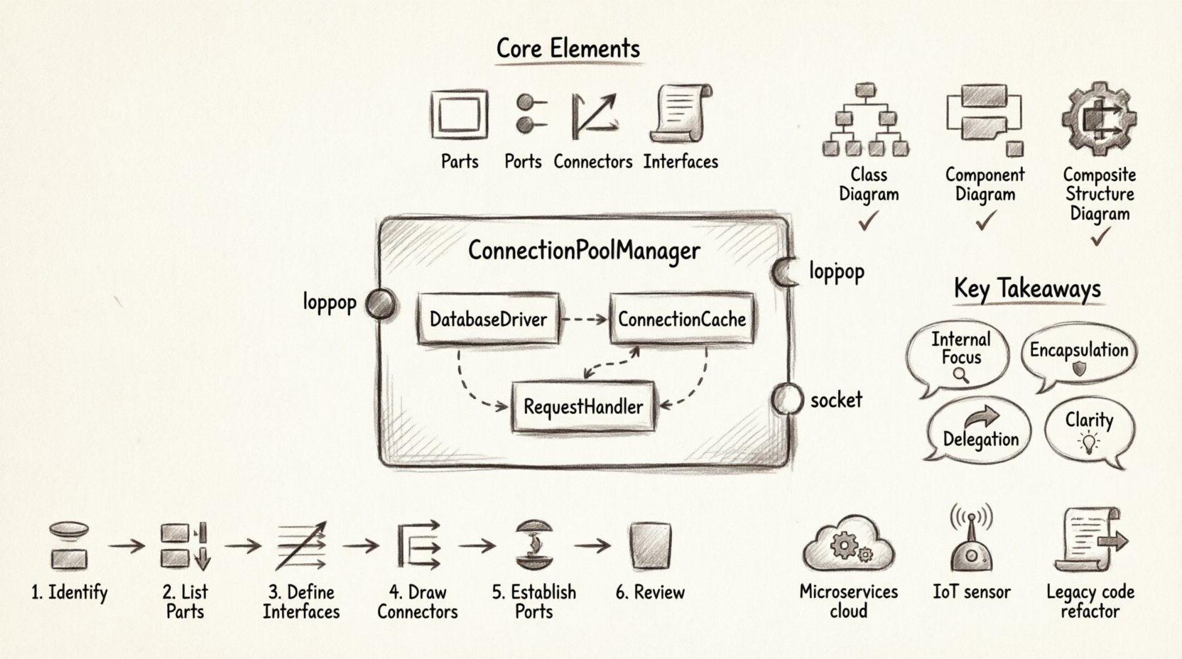
- Parts: The internal components that make up the structure.
- Ports: The points of interaction where external connections occur.
- Connectors: The links that bind parts together internally.
- Interfaces: The contracts that define how parts communicate.
For students, this diagram is particularly valuable when dealing with complex systems where the internal wiring matters as much as the external API. It helps clarify dependencies and reduces coupling within a single unit.
⚙️ Core Elements of the Diagram
To build a composite structure diagram effectively, one must understand its building blocks. Each element serves a specific purpose in defining the internal logic and connectivity.
1. Parts and Part Specifications
A part represents an instance of a classifier that is owned by the composite structure. It is essentially an object living inside another object. The part specification defines the type of the part and can include constraints or multiplicity.
- Multiplicity: Indicates how many instances of a part exist within the structure (e.g., one, many, or zero or more).
- Constraints: Rules that limit how the part can be used or modified.
- Visibility: Just like class attributes, parts can be public, private, or protected, determining their accessibility from outside the structure.
2. Ports
Ports are the interaction points of a composite structure. They define where external connections can be made. Ports encapsulate the interface, hiding the internal complexity from the outside world. This promotes encapsulation and reduces coupling.
- Provided Interface: A port that offers functionality to external elements. It is often shown with a “lollipop” symbol.
- Required Interface: A port that needs functionality from external elements. It is often shown with a “socket” symbol.
- Role Names: Each port can have a role name that describes its specific function within the interaction.
3. Connectors
Connectors link ports together. They define the flow of information or control between parts within the structure. Connectors can be typed to specify the kind of interaction allowed.
- Internal Connectors: Links two ports within the same structure.
- Delegation Connectors: Links an internal port to an external interface, effectively passing requests through the boundary.
- Association: Represents the link between two parts.
4. Internal Nodes
Internal nodes represent the boundaries or regions within the structure. They help organize the internal layout and can be used to group related parts. This is useful for visualizing logical separation within a single composite unit.
📊 Comparison: CSD vs. Class Diagram vs. Component Diagram
Students often confuse the Composite Structure Diagram with other UML diagram types. Understanding the distinctions is crucial for selecting the right tool for the job.
| Diagram Type | Focus | Best Used For |
|---|---|---|
| Class Diagram | Static structure of all classes and relationships | Overview of the entire system data model |
| Component Diagram | High-level physical or logical components | Deployment and system boundaries |
| Composite Structure Diagram | Internal structure of a single classifier | Deep dive into object composition and internal wiring |
While a class diagram shows that Class A has a relationship with Class B, a Composite Structure Diagram shows how Class A is built using instances of Class B internally. This level of detail is vital for understanding delegation and containment.
🛠️ Practical Application: Connecting Theory to Reality
Theoretical knowledge is only valuable if it can be applied. Here are several scenarios where a Composite Structure Diagram adds significant value in a student’s project or professional work.
1. Microservices Architecture
In modern distributed systems, services often contain multiple internal modules. A CSD can illustrate how a single service node is composed of sub-modules that handle authentication, logging, and data processing. It clarifies how data flows between these internal modules before being exposed via an API port.
- Scenario: A User Service.
- Internal Parts: Validation Module, Database Connector, Cache Manager.
- Port: REST API Endpoint.
2. Hardware-Software Integration
Embedded systems often require precise modeling of how software interacts with physical hardware. A CSD allows students to model a controller class that contains internal hardware drivers as parts. This visualizes the abstraction layer between the application logic and the physical device.
- Scenario: IoT Temperature Sensor Controller.
- Internal Parts: ADC Driver, Signal Processor, Data Formatter.
- Interface: Required interface for the sensor hardware.
3. Legacy System Refactoring
When analyzing old codebases, understanding the internal composition of complex classes is necessary before refactoring. A CSD helps identify tightly coupled parts that should be separated or interfaces that need to be exposed.
📝 Step-by-Step Modeling Workflow
Creating a Composite Structure Diagram requires a systematic approach. Follow these steps to ensure accuracy and clarity in your designs.
- Identify the Classifier: Start with the class or component you wish to analyze. This will be the main frame of the diagram.
- List Internal Parts: Identify the objects that are owned by the classifier. These become the parts inside the structure.
- Define Interfaces: Determine which interfaces each part provides or requires. This defines their capabilities.
- Draw Connectors: Connect the parts that need to communicate. Ensure all required interfaces are satisfied by provided interfaces.
- Establish Ports: Place ports on the boundary of the structure where external connections occur. Use delegation connectors if an internal part needs to be accessible externally.
- Review Constraints: Add any multiplicity or constraint notes to ensure the model adheres to business rules.
⚠️ Common Pitfalls to Avoid
Even experienced designers make mistakes when modeling internal structures. Being aware of these common errors will help you create cleaner, more maintainable diagrams.
- Overcomplication: Do not include every single attribute in a CSD. Focus on the structural connections, not the data values.
- Ignoring Delegation: If an internal part is accessed from outside, use a delegation connector. Connecting directly to the internal part violates encapsulation.
- Missing Interface Types: Clearly distinguish between provided and required interfaces. Ambiguity here leads to confusion about data flow direction.
- Redundancy: If a class diagram already shows the relationship clearly, do not repeat it in the CSD unless the internal wiring adds new information.
🎓 Tips for Students
Learning this diagram type can be challenging. Here are some practical tips to aid your understanding and application.
- Start Simple: Begin with a structure containing only two parts and one connector. Gradually increase complexity as you become comfortable.
- Use Annotations: Add text notes to explain complex logic that cannot be shown graphically.
- Cross-Reference: Always keep your Class Diagram open. Ensure the parts in the CSD exist in the Class Diagram.
- Focus on Flow: Trace the path of a request through the internal parts. If the path is unclear, the diagram is likely incorrect.
🔄 Real-World Example: Database Connection Pool
Consider a software module responsible for managing database connections. This is a classic scenario where a Composite Structure Diagram shines.
Structure: ConnectionPoolManager
- Part 1: DatabaseDriver (Provides connection capability)
- Part 2: ConnectionCache (Stores active connections)
- Part 3: RequestHandler (Manages incoming requests)
Connectors:
- ConnectionCache connects to DatabaseDriver to request new connections.
- RequestHandler connects to ConnectionCache to retrieve existing connections.
Ports:
- Port A: External interface for the application to request a connection.
- Delegation: Port A delegates to RequestHandler.
This visualization makes it immediately clear how a request is processed internally, showing the dependency on the cache and the driver without cluttering the external view.
🚀 Future-Proofing Your Design Skills
As software systems become more distributed and complex, the ability to model internal structures becomes increasingly important. Modern architectures like microservices, serverless functions, and cloud-native applications rely heavily on clear interface definitions and internal component isolation. The Composite Structure Diagram provides the vocabulary to describe these relationships precisely.
By mastering this tool, you demonstrate a deeper understanding of system design principles. You move beyond writing code to designing systems. This shift in perspective is what distinguishes a junior developer from a senior engineer.
🧩 Summary of Key Takeaways
- Internal Focus: CSDs are for looking inside a classifier, not at the whole system.
- Parts and Ports: Understand that parts are internal instances, and ports are the interaction points.
- Encapsulation: Use ports to hide internal complexity from the outside world.
- Delegation: Use delegation connectors to expose internal functionality safely.
- Clarity: The goal is to reduce confusion about how components interact internally.
Whether you are designing a simple class or a complex distributed service, the Composite Structure Diagram offers a lens to see the machinery at work. It turns abstract relationships into concrete connections. As you continue your studies, practice applying these concepts to your own projects. Sketching out the internal structure of your code will inevitably lead to better, more modular, and more maintainable software.
Remember that diagrams are living documents. They should evolve as the system evolves. Keep your Composite Structure Diagrams up to date to ensure they remain a valuable resource for your team and your future self.