


In modern software architecture, understanding the internal composition of a class is just as critical as understanding its external interface. While standard Class Diagrams provide a high-level view of system components, they often fail to depict how those components interact internally. This is where the Composite Structure Diagram becomes essential. It offers a granular look at the internal parts of a classifier and their collaborations. This guide explores the anatomy, roles, and patterns inherent in this UML notation, providing a clear framework for modeling complex internal structures.
🔍 What Is a Composite Structure Diagram?
A Composite Structure Diagram is a type of UML structure diagram that shows the internal structure of a classifier. It breaks down a class into its constituent parts, showing how they are connected and how they interact with the outside world. Think of it as an X-ray of a class. Instead of just seeing a box with method signatures, you see the machinery inside.
This diagram is particularly useful when:
- Modeling complex systems with nested components.
- Defining internal interfaces and ports.
- Visualizing the deployment of parts within a larger structure.
- Clarifying the difference between a class’s external behavior and its internal implementation.
By utilizing this diagram, architects can reduce cognitive load. Instead of tracing connections across multiple files or modules, the internal logic is encapsulated within a single, clear view. This clarity supports better maintenance and more robust design decisions.
🧩 Anatomy of the Composite Structure Diagram
To model effectively, one must understand the specific elements that make up this diagram. Each element serves a distinct semantic purpose. Misusing these elements can lead to confusion during implementation.
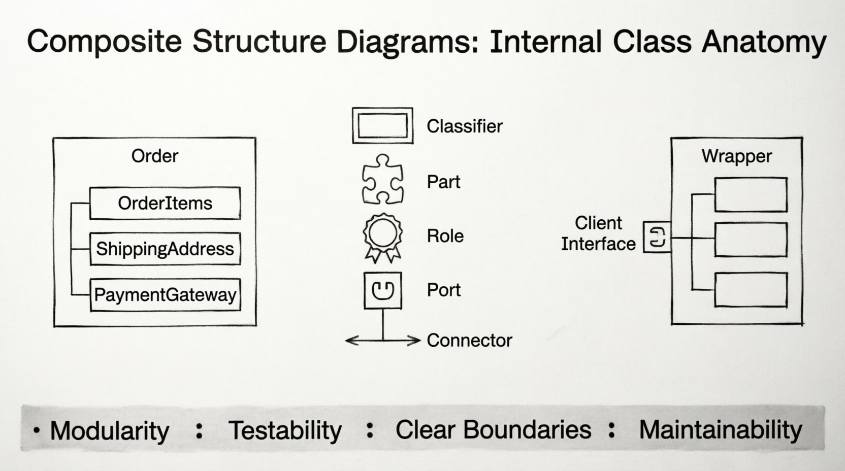
1. The Classifier (Composite)
The classifier acts as the container for the internal structure. It is typically represented by a class symbol. However, in this context, it is often split into two sections: the outer section representing the classifier itself, and an inner section (often a rectangle with a tab) representing the internal structure.
2. Parts
A Part is a component that resides inside the composite structure. It represents a specific instance of a classifier that is owned by the composite. For example, a Car class might have parts like Engine, Wheel, and SteeringSystem.
Key characteristics of Parts include:
- Ownership: The part is owned by the composite. If the composite is destroyed, the parts are typically destroyed as well.
- Multiplicity: Parts can have multiplicity constraints (e.g., a Car has exactly one Engine, but can have four or more Wheels).
- Visibility: Parts can be public, private, or protected, determining how they are accessed from outside the composite.
3. Roles
A Role describes the functionality provided or required by a part within the context of the composite structure. A single part might play multiple roles at different times or in different contexts. This separation allows for greater flexibility in design.
Consider a USBStick part inside a Computer composite. The part might play the role of Storage when providing data, but the role of Interface when connecting to the port.
4. Ports
Ports are interaction points where a composite structure can interact with the outside world. They define the boundary between the internal structure and its environment. Ports can be:
- Providing: The composite offers functionality through this port.
- Requiring: The composite needs functionality provided by another component through this port.
5. Connectors
Connectors establish associations between roles and ports. They define how data or control flows between the internal parts and the external environment. Connectors ensure that the correct interface is used for communication.
📊 Class Roles and Responsibilities
Understanding the specific roles assigned to parts is crucial for accurate modeling. The following table outlines the distinctions between common roles found in composite structures.
| Element | Definition | Usage Context |
|---|---|---|
| Part | An owned instance of a classifier within the structure. | Defines ownership and lifecycle. |
| Role | A named interface or capability provided by a part. | Defines specific behaviors or contracts. |
| Port | A boundary for interaction with the environment. | Defines entry and exit points for the composite. |
| Connector | A link between a role and a port (or another role). | Defines the path of interaction. |
🧠 Design Patterns in Composite Structure
Several design patterns are naturally visualized using composite structure diagrams. These patterns solve recurring problems in software architecture. By mapping these patterns to the diagram elements, developers can ensure the structure supports the intended behavior.
1. The Composite Pattern
The Composite Pattern allows clients to treat individual objects and compositions of objects uniformly. In a Composite Structure Diagram, this is represented by a recursive structure.
- Leaf Component: A part that does not have children. It performs the basic operation.
- Composite Component: A part that can have children (other parts). It delegates operations to its children.
For example, a Filesystem structure can be modeled where Directory is a composite containing File parts. Both Directory and File implement a common Readable interface, allowing the system to treat them consistently.
2. The Facade Pattern
The Facade Pattern provides a simplified interface to a complex subsystem. In a composite structure, this is often seen as a part that wraps multiple internal parts.
- A
Facadepart contains multiple internal parts (e.g.,DatabaseManager,Logger,Cache). - External interactions occur through the
Facadeport. - The internal parts are hidden from the external view.
This reduces coupling. External clients depend only on the facade, not on the specific implementations of the internal parts.
3. The Proxy Pattern
The Proxy Pattern controls access to an object. In the diagram, this is visualized as a part that mediates between the client and the real subject.
- A
Proxypart holds a reference to theRealSubjectpart. - Interactions are routed through the proxy first.
- The proxy can perform additional actions (like logging or permission checks) before delegating to the real subject.
🛠️ Implementation Strategies
Translating a Composite Structure Diagram into code requires careful attention to language features and architectural constraints. Different programming paradigms support these concepts in varying degrees.
Type Safety and Interfaces
When implementing roles, it is best to define strict interfaces. This ensures that the parts adhere to the expected contracts. Using abstract base classes or interface definitions helps maintain the integrity of the design.
- Define Roles Explicitly: Do not rely on implicit behavior. Define the methods that constitute a role.
- Enforce Multiplicity: Ensure that the code enforces the cardinality defined in the diagram (e.g., checking if a collection has the correct number of elements).
Dependency Management
The diagram highlights dependencies between parts. In implementation, this translates to dependency injection or constructor injection.
- Constructor Injection: Parts are created and injected when the composite is instantiated.
- Setter Injection: Parts are assigned after instantiation, useful for optional dependencies.
- Service Locator: Parts are retrieved from a central registry, though this can increase coupling.
🚧 Common Misinterpretations
Even experienced architects can make mistakes when modeling internal structures. The following table highlights common errors and their corrections.
| Misinterpretation | Correct Approach |
|---|---|
| Using the diagram for sequence logic. | Use this diagram for structure, not behavior. Use Sequence Diagrams for logic flow. |
| Naming parts after methods. | Name parts after nouns (objects/components), methods belong inside the part. |
| Overusing Ports for internal links. | Use Ports for external boundaries. Use Connectors for internal part-to-part links. |
| Ignoring Lifecycle Management. | Ensure ownership rules (composition vs aggregation) are respected in code. |
🔗 Integration with Other Diagrams
A Composite Structure Diagram does not exist in isolation. It integrates with other UML diagrams to provide a complete picture of the system.
Class Diagrams
The Class Diagram provides the static structure of the system. The Composite Structure Diagram provides the internal detail of specific classes from the Class Diagram. They complement each other. You start with the Class Diagram to identify the system boundaries, then drill down into specific classes using Composite Structure Diagrams.
Sequence Diagrams
Sequence Diagrams show the flow of messages. A Composite Structure Diagram defines the targets of those messages. When a message arrives at a Port in the Sequence Diagram, the Composite Structure Diagram explains how that message is routed internally to the correct Part.
Deployment Diagrams
Deployment Diagrams show where components are physically located. Composite Structure Diagrams show how components are logically organized. A single deployment node might host multiple composites, and a single composite might span multiple nodes in distributed systems.
📐 Best Practices for Modeling
To maintain clarity and utility, adhere to the following guidelines when creating these diagrams.
- Keep it Flat: Avoid excessive nesting. If a structure becomes too deep, consider splitting the classifier into multiple smaller classes.
- Use Meaningful Names: Part names should be descriptive. Avoid generic names like
Part1orComponentA. - Minimize Cross-References: Keep connections local to the structure. If a part needs to reach outside frequently, it might be a design smell indicating a need for refactoring.
- Document Roles: Always document the interface that a role implements. This clarifies the contract between parts.
- Version Control: Treat these diagrams as code. Store them in version control to track structural changes over time.
🚀 Architectural Implications
Adopting Composite Structure Diagrams has long-term benefits for the software lifecycle. It forces developers to think about modularity early in the design process.
- Modularity: Clear boundaries between parts encourage loose coupling.
- Testability: Parts can be tested in isolation if their ports and roles are well-defined.
- Scalability: It is easier to scale a system with well-defined composite structures than one with tangled dependencies.
- Maintainability: When a part fails, the diagram helps identify exactly where the failure originates within the composite.
Furthermore, this level of detail aids in documentation for new team members. A new developer can look at the diagram to understand not just what a class does, but how it is built. This reduces the onboarding time and minimizes the risk of introducing bugs during refactoring.
🔬 Case Study: E-Commerce Order System
Consider an Order Management System. A Order class is complex. It contains items, shipping details, and payment processing logic.
Without a Composite Structure Diagram, the Order class might appear as a monolithic block. With the diagram:
- Parts:
OrderItems,ShippingAddress,PaymentGateway. - Roles:
CalculationRole(for total price),ValidationRole(for address). - Ports:
ExternalOrderPort(receives order from user),InternalPaymentPort(sends payment request).
This breakdown reveals that the PaymentGateway part is a dependency that might change. By isolating it as a part with a defined port, the system can swap payment providers without altering the Order class structure. This modularity is a direct result of the composite structure modeling.
🛡️ Security Considerations
Security is often overlooked in structural diagrams, but the Composite Structure Diagram provides a place to model it.
- Access Control: Ports can be used to define secure entry points. Only authenticated requests should reach specific ports.
- Data Isolation: Parts can represent security boundaries. Sensitive data should reside in parts that are not exposed via public ports.
- Interface Validation: Roles can enforce input validation. The
ValidationRoleensures data integrity before it reaches the core logic.
By visualizing these boundaries, architects can identify potential vulnerabilities where sensitive data might leak through an unintended role or port.
🔄 Evolution of the Diagram
As requirements change, the composite structure must evolve. This is not a static artifact. It should be updated alongside code changes.
- Refactoring: If a part grows too large, split it into a new composite structure.
- Feature Addition: Add new parts to handle new functionality, ensuring existing roles are not broken.
- Deprecation: Remove parts that are no longer used, updating connectors to reflect the new reality.
Maintaining this synchronization ensures the diagram remains a trusted source of truth. If the diagram is out of date, it becomes noise rather than signal.
📝 Summary of Structural Elements
To recap, the core elements that define the Composite Structure Diagram include:
- Classifier: The container for the internal structure.
- Part: A component owned by the classifier.
- Role: The functionality provided or required by a part.
- Port: The interaction point with the environment.
- Connector: The link between roles and ports.
These elements work together to create a robust model of system internals. They allow for precise communication between architects and developers.
🎯 Final Architectural Considerations
Effective use of the Composite Structure Diagram requires discipline. It is easy to over-model and create diagrams that are too complex to maintain. The goal is clarity, not complexity. Use this tool when the internal structure adds value to the understanding of the system.
When applied correctly, it bridges the gap between high-level design and low-level implementation. It provides a blueprint for building systems that are modular, testable, and secure. By focusing on parts, roles, and connections, teams can construct software that stands the test of time.
Remember that the diagram is a means to an end. The end is a well-architected system. Use the diagram to achieve that end, but do not let the diagram become the system itself. Code and design must remain aligned, with the diagram serving as a guide rather than a constraint.