


Composite Structure Diagrams serve as the architectural blueprints for complex systems. They reveal the internal organization of a classifier, showing how parts interact to fulfill the classifier’s responsibilities. However, when these diagrams contain structural inconsistencies, the entire model becomes unreliable. Identifying and repairing these weak links is essential for maintaining system integrity and ensuring clear communication among stakeholders.
When a composite structure diagram fails to accurately represent the intended architecture, it can lead to implementation errors, integration failures, and significant rework later in the development lifecycle. This guide provides a rigorous approach to diagnosing and resolving flaws within these diagrams. We will examine the anatomy of the diagram, identify common failure points, and establish a workflow for validation.
🏗️ Understanding the Anatomy of a Composite Structure Diagram
Before troubleshooting, one must understand the fundamental building blocks. A composite structure diagram is not merely a collection of boxes; it is a representation of composition relationships and interaction protocols. The following components form the core of this modeling technique:
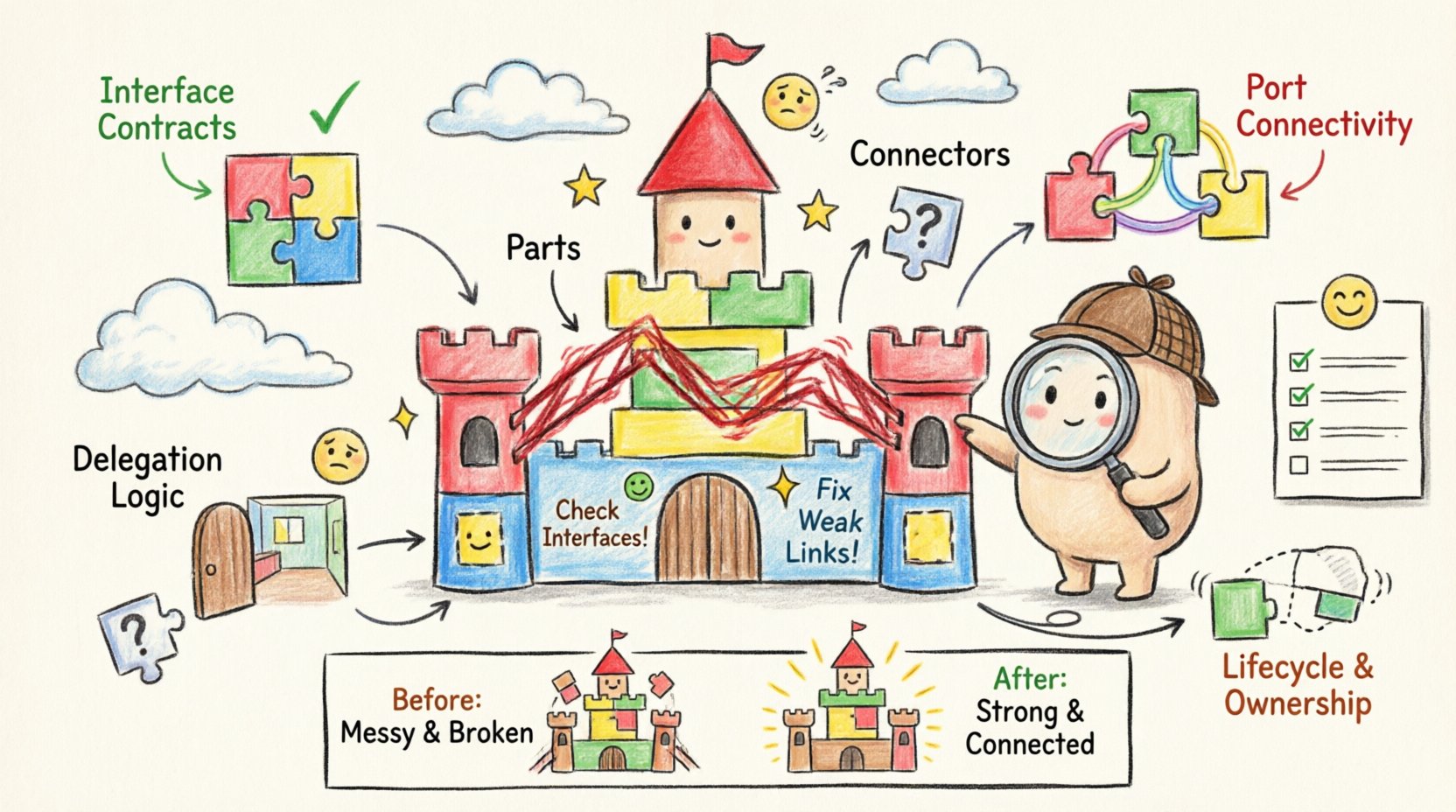
- Parts: These are the instances of classifiers that exist within the composite structure. They represent the concrete components that make up the whole.
- Ports: Defined interfaces at the boundary of a part. Ports specify how a part interacts with its environment or other parts within the composite structure.
- Interfaces: Contracts that define a set of operations provided or required by a classifier. In composite structures, interfaces ensure type compatibility between connected parts.
- Connectors: Links that establish communication paths between ports. Connectors define the flow of data or control signals.
- Roles: Labels that describe the function a part plays at a specific port. A single part may play multiple roles depending on the context of the connection.
- Delegation Connectors: Specialized connectors that route signals from an internal port to an external interface of the composite structure.
Weaknesses often arise when these elements are misaligned. A part might request an interface it does not possess, or a connector might bridge incompatible data types. Recognizing the distinct role of each element allows for targeted troubleshooting.
🚨 Common Flaws and Weak Links
In practice, composite structure diagrams frequently suffer from specific types of structural errors. These flaws degrade the utility of the model and create ambiguity for developers. Below are the most prevalent issues encountered during modeling sessions.
1. Interface Mismatch Errors
One of the most critical errors occurs when a connector links two ports that do not share a compatible interface. This is often referred to as a type mismatch. If Part A requires a WriteAccess interface but Part B only provides ReadAccess, the connection is logically invalid. The diagram suggests functionality that cannot be implemented without modifying the underlying code.
2. Unconnected or Dangling Parts
Parts that are defined within the composite structure but have no incoming or outgoing connections are often indicative of incomplete modeling. While some parts may be optional, a lack of connection points raises questions about their lifecycle and purpose. Are they initialized but unused? Is the logic missing? Dangling parts clutter the diagram and obscure the primary flow of information.
3. Circular Dependencies
While some interdependence is natural, circular dependencies between internal parts can lead to instantiation paradoxes. If Part A cannot be created without Part B, and Part B cannot be created without Part A, the system is deadlocked. In a diagram, this appears as a closed loop of connections without an external entry point to trigger initialization.
4. Incorrect Delegation
Delegation connectors are used to expose internal ports to the outside world. A common flaw is delegating the wrong interface or failing to delegate at all. If an internal service needs to be accessible externally, but the delegation connector is missing, the composite structure acts as a black box when it should be transparent. Conversely, over-delegating can expose internal implementation details that should remain encapsulated.
5. Lifecycle Inconsistencies
Composite structures often imply ownership. If the composite structure is destroyed, its parts should typically be destroyed as well. However, diagrams often fail to explicitly model this lifecycle dependency. A weak link occurs when a part is shown as persistent while the composite that owns it is transient. This discrepancy creates ambiguity regarding resource management and memory handling.
🛠️ Step-by-Step Troubleshooting Workflow
Fixing a flawed diagram requires a systematic approach. Ad-hoc changes often introduce new errors. The following workflow ensures that every modification is validated against the architectural intent.
Step 1: Audit the Interface Contracts
Begin by reviewing every interface definition attached to a port. Verify that the operation signatures match across the connector. Ensure that the multiplicity of the interface matches the requirement. If a port requires one instance of an interface, the connected part must provide exactly one, not zero or multiple.
- Check operation names for exact spelling.
- Verify parameter types are compatible.
- Ensure return types align with the caller’s expectations.
Step 2: Validate Port Connectivity
Inspect every connector. Does it bridge two valid ports? Is the directionality correct? Some interfaces are unidirectional, meaning signals flow only one way. Connecting them bidirectionally without a proper proxy or adapter creates a structural weakness.
- Trace the path from the source port to the destination port.
- Confirm that no intermediate steps are missing.
- Ensure that required interfaces are actually provided by the target part.
Step 3: Review Delegation Logic
Examine the boundary of the composite structure. Are the external interfaces correctly mapped to internal ports? If a service is exposed, trace it back to the internal implementation. If the delegation is broken, the external caller will not reach the internal logic.
- Map each external interface to an internal port.
- Ensure no internal port is exposed unless necessary.
- Verify that the delegation connector type matches the interface type.
Step 4: Check Lifecycle and Ownership
Review the ownership relationships. Determine if parts are shared or owned. Owned parts are destroyed with the composite. Shared parts persist independently. Ensure the diagram reflects the intended resource management strategy.
📊 Diagnostic Checklist for Structural Integrity
To facilitate quick identification of issues, use the following table as a reference during your review process. This checklist categorizes symptoms, potential causes, and corrective actions.
| Symptom | Potential Cause | Corrective Action |
|---|---|---|
| Connector shows error flag | Interface type mismatch | Align interface definitions between ports |
| Part has no connections | Missing dependency logic | Add required connectors or remove unused part |
| External call fails internally | Broken delegation | Re-link internal port to external interface |
| Diagram is too complex | Over-nesting of composites | Refactor into separate sub-structures |
| Loop detected in flow | Circular dependency | Reorder initialization sequence |
| Role is undefined | Missing role label | Assign a descriptive role to the connector end |
🧩 Advanced Considerations for Complex Structures
As systems grow, composite structures become nested. A part within a composite may itself be a composite. This nesting introduces layers of abstraction that can obscure weak links. Handling these advanced scenarios requires attention to detail.
Nested Composite Structures
When a part is a composite itself, its internal structure must be accessible if delegation is required. However, deep nesting can make traceability difficult. If a signal must pass through three layers of composition, each layer must correctly delegate the request. A break at any layer renders the connection useless.
- Ensure each nesting level has a defined external interface.
- Verify that delegation chains are complete from the root to the leaf.
- Limit nesting depth to maintain readability and manageability.
Behavioral Integration
While composite structure diagrams focus on static structure, they often imply behavior. A part may trigger a state change in another part. If the diagram does not align with the state machine or activity diagram, the structural link is weak. Consistency between structural and behavioral models is key.
- Cross-reference with state diagrams to ensure valid transitions.
- Verify that structural connections support the intended behavioral flow.
- Check that ports support the operations required by the state logic.
Multiplicity and Cardinality
Connections often involve multiple instances. A single composite part might contain multiple instances of a sub-part. The diagram must accurately reflect the multiplicity constraints. If a connector allows one-to-many, the receiving port must be able to handle multiple signals or connections. Ignoring multiplicity leads to runtime errors.
- Specify multiplicity explicitly on connector ends.
- Ensure the receiving part can instantiate the required number of objects.
- Validate that the interface supports the volume of traffic implied by the multiplicity.
🛡️ Best Practices for Maintenance
Once the diagram is fixed, maintaining its integrity is crucial. Modeling is not a one-time task; it is a continuous process. Adopting best practices reduces the likelihood of future degradation.
Consistent Naming Conventions
Clear naming reduces cognitive load. Use standard naming for ports and interfaces. Avoid generic names like Port1 or InterfaceA. Instead, use descriptive names that indicate function, such as AuthService or DataWriter. This makes it easier to spot mismatches during a visual review.
Modularization
Break large diagrams into smaller, manageable sub-diagrams. If a composite structure exceeds a certain complexity, split the internal structure of a major part into its own diagram. This reduces visual noise and isolates errors to specific modules.
Regular Reviews
Schedule periodic audits of the composite structure diagrams. As requirements change, the structure must evolve. A diagram that was valid six months ago may now contain obsolete links. Regular reviews ensure that the model remains synchronized with the codebase.
📝 Final Thoughts on Structural Reliability
A robust composite structure diagram is more than a visual aid; it is a contract between design and implementation. Weak links in this structure propagate errors downstream, affecting code quality and system stability. By systematically auditing interfaces, validating connections, and respecting lifecycle constraints, modelers can ensure high fidelity in their architectural representations.
The process of fixing these diagrams requires patience and attention to detail. It involves understanding not just the syntax of the modeling language, but the semantics of the system being built. When every part, port, and connector is verified, the resulting architecture stands on a solid foundation, ready for development and deployment.
Adopting a disciplined approach to troubleshooting minimizes rework and maximizes the value of the modeling effort. Focus on clarity, consistency, and correctness. These principles form the bedrock of effective system design.