
Mastering ATM Logic: A UML Sequence Diagram Guide with Visual Paradigm
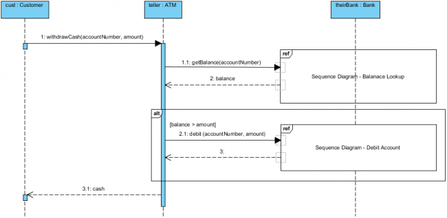
In the realm of software engineering, Sequence Diagrams are the gold standard for visualizing the dynamic behavior of a system. Unlike static diagrams that show structure, sequence diagrams illustrate how objects interact over time to perform a specific task.
In this tutorial, we will dissect a complex banking scenario: an ATM withdrawal. We will walk through the architecture, the specific interaction logic, and the advanced modeling features (like ref and alt) used to manage complexity. All concepts presented here are implemented using Visual Paradigm, the industry-leading tool for UML modeling.
Understanding the Participants (Lifelines)
Before diving into the interactions, we must identify the actors in our system. In a sequence diagram, these are represented as vertical dashed lines, often called Lifelines. Each lifeline represents a distinct object or system component that participates in the process.
In our diagram, we have three critical participants:
- cust : Customer: The initiating actor. This is the user interacting with the interface.
- teller : ATM: The central processing unit. This object coordinates the request, handling the logic between the user and the backend bank system.
- theirBank : Bank: The data source. This represents the external financial institution that holds the account records.
Decoding the Interaction Flow
The flow of the diagram follows a top-to-bottom timeline. Messages are arrows connecting these lifelines. Let’s break down the specific steps shown in the architecture.
1. The Initiation and Balance Check
The process begins when the Customer initiates a withdrawal. This is represented by a solid arrow labeled 1: withdrawCash(accountNumber, amount).
Upon receiving this request, the ATM does not immediately process the cash. Instead, it must validate the account. It sends a synchronous message to the Bank: 1.1: getBalance(accountNumber).
The Bank processes this and returns the data. We see this as a dashed arrow with an open head, labeled 2: balance. This represents a return message.
2. The “Ref” (Reference) Fragment
Notice the box surrounding the balance lookup interaction. This is a Reference Fragment (indicated by the ref label in the top-left corner of the box). This is a crucial modeling technique.
When a process is too complex to draw in full detail within the current diagram, or if it is a standard library function used elsewhere, we encapsulate it in a ref box. This box implies that there is a separate, detailed sequence diagram (in this case, named Sequence Diagram – Balance Lookup) that describes exactly how the balance is retrieved. It allows the high-level diagram to remain clean and readable.
3. The “Alt” (Alternative) Fragment
Once the ATM has the balance, it must decide whether to dispense cash. This is handled by the Alternative Fragment (labeled alt).
Inside the alt frame, there is a condition: [balance > amount]. This acts as a gatekeeper. The logic dictates that the subsequent steps only occur if the customer’s balance is strictly greater than the requested withdrawal amount.
Deep Dive: Debiting the Account
If the condition [balance > amount] evaluates to true, the flow proceeds to the debit process:
- The ATM sends a message to the Bank:
2.1: debit(accountNumber, amount). - Like the balance check, this is a complex operation. It is encapsulated in a Reference Fragment box labeled Sequence Diagram – Debit Account.
- Once the bank successfully deducts the funds, it sends a return message (labeled
3) back to the ATM.
Finally, the ATM completes the transaction by sending the final response to the user: 3.1: cash.
Conclusion
By utilizing Visual Paradigm, we can effectively map out the logic of a banking transaction. The combination of standard messages, return arrows, and advanced fragments like ref and alt allows developers to model complex conditional logic while maintaining a high-level overview of the system architecture.
Mastering these diagrams is essential for clear communication between developers, architects, and stakeholders, ensuring that the logic of “withdrawal” is perfectly understood before a single line of code is written.