


Introduction
In the world of software engineering and system design, understanding how components interact is just as critical as knowing what those components are. While class diagrams provide a static view of the system’s structure, UML Sequence Diagrams offer a dynamic perspective. They are interaction diagrams that detail how operations are carried out, capturing the collaboration between objects over time.
For product managers, architects, and developers, sequence diagrams are indispensable tools for visualizing the flow of logic, identifying bottlenecks, and ensuring that complex use cases are implemented correctly. This guide explores the core concepts, notations, and best practices for creating effective sequence diagrams, complete with PlantUML examples to help you model before you code.
What is a Sequence Diagram?
A UML Sequence Diagram is an interaction diagram that shows how processes operate with one another and in what order. It captures the interaction between objects in the context of a collaboration. The defining characteristic of a sequence diagram is its focus on time.
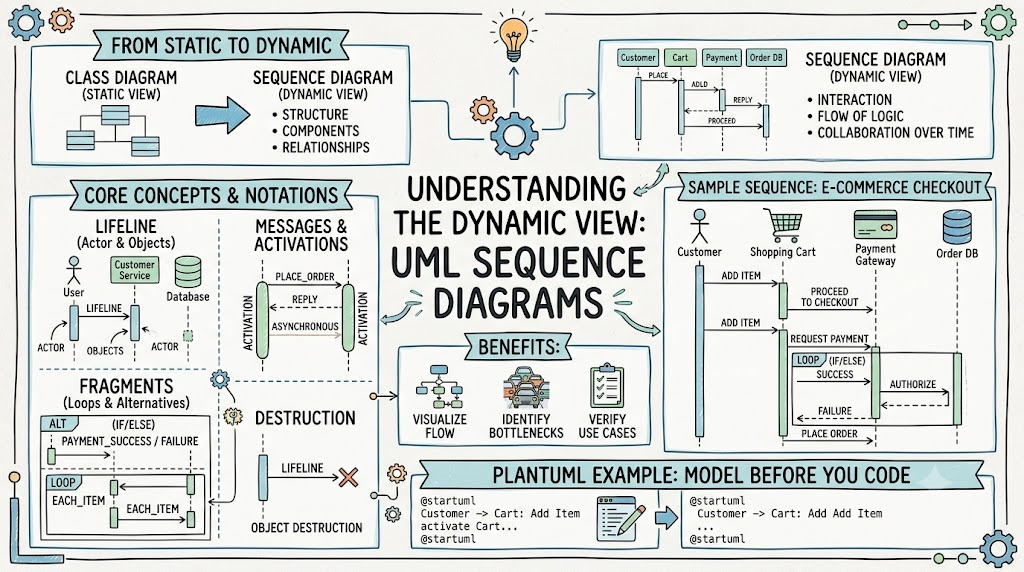
Sequence diagrams are part of the broader UML hierarchy, specifically falling under interaction diagrams. They are used to:
-
Model high-level interactions between active objects in a system.
-
Detail the interaction between object instances within a collaboration that realizes a use case.
-
Visualize the message exchange between subsystems or external systems.

Key Characteristics
-
Time-Focused: The vertical axis represents time progressing downwards.
-
Object-Oriented: The horizontal axis lists the objects or participants involved in the interaction.
-
Dynamic: Unlike static class diagrams, sequence diagrams describe how objects collaborate during runtime.
Sequence Diagrams at a Glance
Understanding the two primary dimensions of a sequence diagram is crucial for reading and creating them effectively.
1. The Object Dimension (Horizontal Axis)
The horizontal axis displays the elements involved in the interaction. These are typically listed from left to right based on when they first participate in the message sequence, though this order can vary. Each element is represented by a Lifeline.
2. The Time Dimension (Vertical Axis)
The vertical axis represents the progression of time. As you move down the diagram, time moves forward.
Note: Time in a sequence diagram is about ordering, not duration. The vertical space between messages does not necessarily correlate to real-time seconds or milliseconds; it simply indicates that one event happens after another.
Core Notations and Elements
To build a sequence diagram, you need to understand the standard UML symbols. Below are the essential notations.
| Notation | Description | Visual Representation |
|---|---|---|
| Actor | Represents a role played by a user, external hardware, or another system. Actors are external to the system being modeled. |  |
| Lifeline | A dashed line representing an individual participant (object or actor) in the interaction. |  |
| Activation (Focus of Control) | A thin rectangle on a lifeline indicating the period during which an element is performing an operation. The top aligns with the start, and the bottom with the completion. |  |
| Call Message | A solid arrow with a filled head, representing an invocation of an operation on the target lifeline. |  |
| Return Message | A dashed arrow with an open head, representing information passed back to the caller. |  |
| Self Message | A message where the sender and receiver are the same lifeline, often indicating internal processing. |  |
| Create Message | A dashed arrow pointing to the header of a new lifeline, indicating object instantiation. |  |
| Destroy Message | An arrow ending in a large “X” on the target lifeline, indicating the object is being destroyed. |  |
| Note | A comment box attached to elements to provide additional context without semantic force. |  |
Message and Focus of Control
An Event is any point in an interaction where something occurs. The Focus of Control (or Execution Occurrence) is visually represented by the activation bar. It highlights exactly when an object is busy executing a task.

Practical Examples with PlantUML
Below are comprehensive examples demonstrating how to model various scenarios using PlantUML syntax.
Example 1: Basic Hotel Reservation System
This example mirrors the classic hotel reservation scenario, showing the interaction between a user interface, the reservation system, and a database.
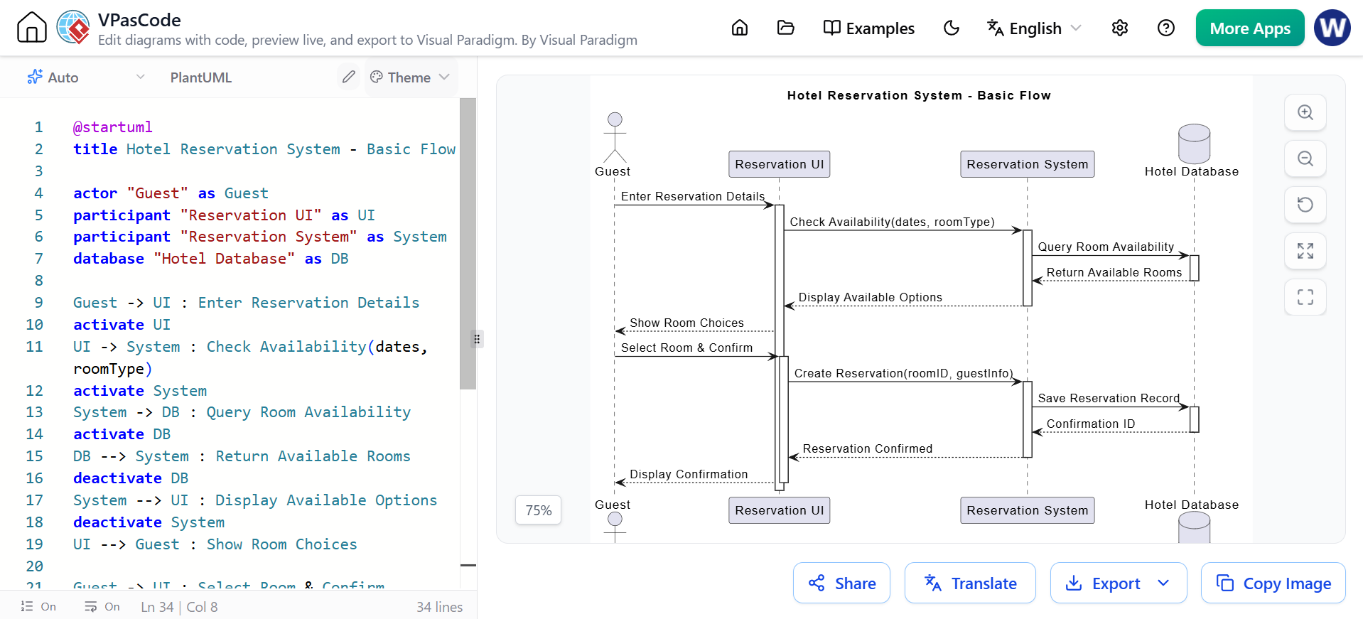
@startuml
title Hotel Reservation System - Basic Flow

actor "Guest" as Guest
participant "Reservation UI" as UI
participant "Reservation System" as System
database "Hotel Database" as DB

Guest -> UI : Enter Reservation Details
activate UI
UI -> System : Check Availability(dates, roomType)
activate System
System -> DB : Query Room Availability
activate DB
DB --> System : Return Available Rooms
deactivate DB
System --> UI : Display Available Options
deactivate System
UI --> Guest : Show Room Choices

Guest -> UI : Select Room & Confirm
activate UI
UI -> System : Create Reservation(roomID, guestInfo)
activate System
System -> DB : Save Reservation Record
activate DB
DB --> System : Confirmation ID
deactivate DB
System --> UI : Reservation Confirmed
deactivate System
UI --> Guest : Display Confirmation
deactivate UI

@enduml
Example 2: Advanced Logic with Combined Fragments
Real-world systems involve conditions, loops, and optional steps. UML 2.0 introduced Combined Fragments to handle these complexities.
Common Fragment Operators:
-
alt: Alternative paths (if/else).
-
opt: Optional path (if).
-
loop: Repeated execution.
-
ref: Reference to another diagram.
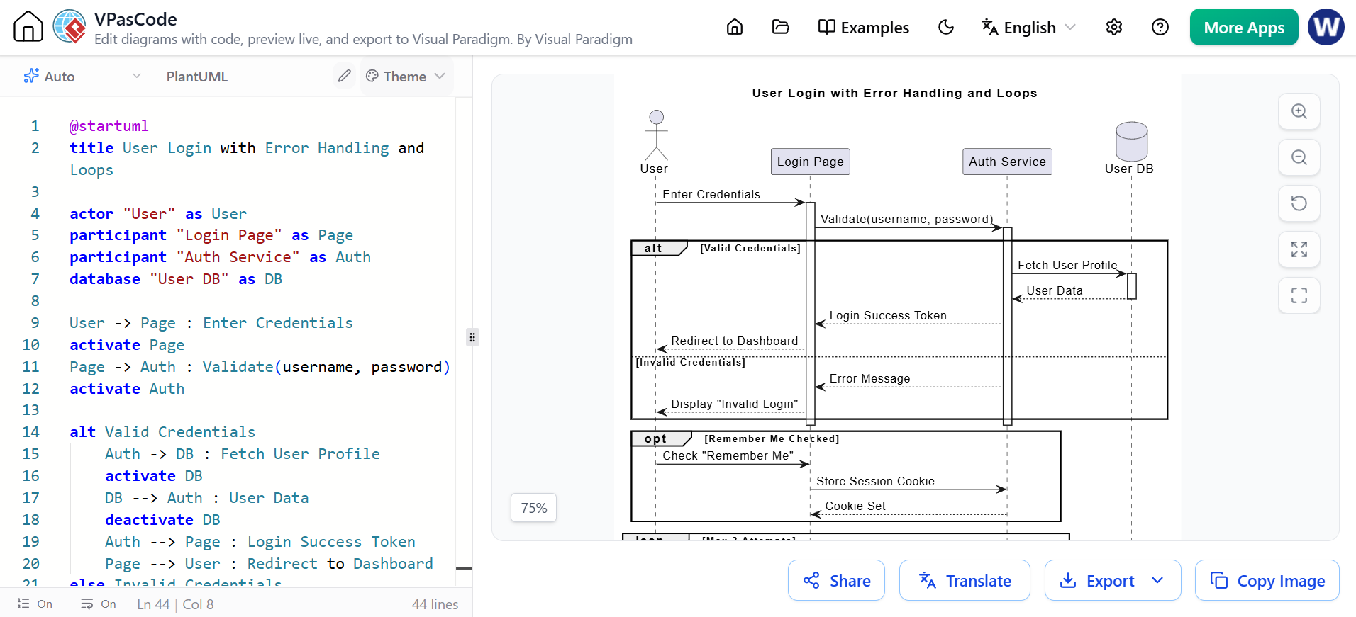
@startuml
title User Login with Error Handling and Loops

actor "User" as User
participant "Login Page" as Page
participant "Auth Service" as Auth
database "User DB" as DB

User -> Page : Enter Credentials
activate Page
Page -> Auth : Validate(username, password)
activate Auth

alt Valid Credentials
    Auth -> DB : Fetch User Profile
    activate DB
    DB --> Auth : User Data
    deactivate DB
    Auth --> Page : Login Success Token
    Page --> User : Redirect to Dashboard
else Invalid Credentials
    Auth --> Page : Error Message
    Page --> User : Display "Invalid Login"
end

deactivate Auth
deactivate Page

opt Remember Me Checked
    User -> Page : Check "Remember Me"
    Page -> Auth : Store Session Cookie
    Auth --> Page : Cookie Set
end

loop Max 3 Attempts
    User -> Page : Retry Login
    break Account Locked
        Page -> Auth : Check Failed Attempts
        Auth --> Page : Account Locked Status
        Page --> User : Show "Account Locked"
    end
end

@enduml
Example 3: Object Creation and Destruction
This example demonstrates the lifecycle of an object, from creation to destruction.
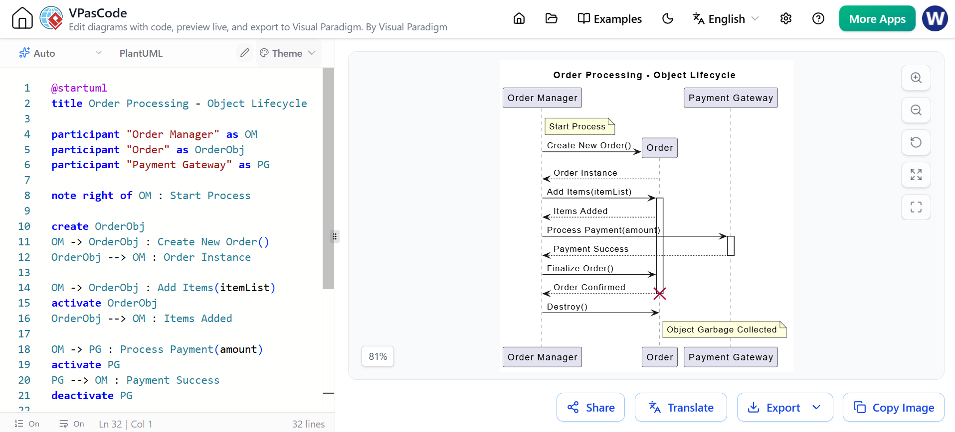
@startuml
title Order Processing - Object Lifecycle

participant "Order Manager" as OM
participant "Order" as OrderObj
participant "Payment Gateway" as PG

note right of OM : Start Process

OM -> OrderObj : Create New Order()
create OrderObj
OrderObj --> OM : Order Instance

OM -> OrderObj : Add Items(itemList)
activate OrderObj
OrderObj --> OM : Items Added

OM -> PG : Process Payment(amount)
activate PG
PG --> OM : Payment Success
deactivate PG

OM -> OrderObj : Finalize Order()
OrderObj --> OM : Order Confirmed

OM -> OrderObj : Destroy()
destroy OrderObj
note right of OrderObj : Object Garbage Collected

deactivate OrderObj
@enduml
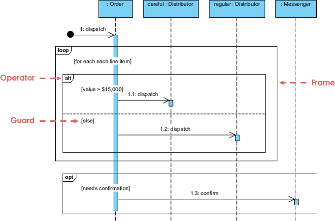
Sequence Fragments Deep Dive
Sequence fragments allow you to model complex logic without cluttering the main flow. A fragment is represented by a box (frame) enclosing a portion of the interaction.

| Operator | Fragment Type | Description |
|---|---|---|
| alt | Alternative | Multiple fragments where only one executes based on a condition (like if-else). |
| opt | Optional | Executes only if the condition is true (like a simple if statement). |
| par | Parallel | Fragments run concurrently. |
| loop | Loop | Executes multiple times based on a guard condition. |
| break | Break | Exits the surrounding interaction if the condition is met (exception handling). |
| ref | Reference | References an interaction defined in another diagram for modularity. |
Combined Fragment Example
Modeling Use Case Scenarios
Sequence diagrams are heavily used in requirements engineering to refine use cases into specific scenarios.
-
Use Case: A collection of interactions between actors and the system.
-
Scenario: A single path through a use case (e.g., the “Happy Path” or an “Error Path”).

By mapping each scenario to a sequence diagram, teams can ensure that all functional requirements are accounted for before development begins.
Why Model Before Code?
You might ask, “Why draw a diagram when I can just write the code?” Here are the key benefits:
-
Abstraction: Sequence diagrams operate at a level slightly above code, focusing on logic flow rather than syntax.
-
Language Neutrality: They can be understood by stakeholders regardless of the programming language used (Java, Python, C#, etc.).
-
Collaboration: Non-coders (Product Managers, Business Analysts) can contribute to and validate the logic.
-
Testing & UX: They serve as excellent blueprints for test cases and can inform UX wireframing by clarifying system responses.
Conclusion
UML Sequence Diagrams are a powerful tool for visualizing the dynamic behavior of systems. By mastering the notations—lifelines, activations, messages, and combined fragments—you can clearly communicate complex interactions among team members. Whether you are modeling a simple login flow or a complex distributed system, sequence diagrams bridge the gap between requirements and implementation.
For those looking to create professional-grade diagrams with ease, Visual Paradigm offers a robust suite of UML modeling tools. Its Community Edition is an international award-winning modeler that is intuitive, easy-to-use, and completely free, making it an excellent choice for learning and practicing UML faster and better.
Free Download Visual Paradigm Community Edition
Related posts:
 Avoiding Pitfalls with AI Activity Diagrams: Streamlining Content Approval & Publishing Cycle
 A Practical Case Study on Unified Modeling Language (UML) Implementation in Modern Software Development
 Bridging the Gap: A Comprehensive Guide to As-Is/To-Be Analysis Using Sequence Diagrams
 UML Sequence Diagrams for Microservices: A Specific Focus for Developers