


Welcome to the world of Systems Modeling Language (SysML). If you have ever felt overwhelmed by the dense terminology surrounding systems engineering, you are not alone. The field of modeling can seem like a fortress built of acronyms and abstract concepts. This guide is designed to dismantle those barriers. We will walk through the core principles of SysML without relying on confusing jargon. Our goal is clarity, practical application, and a solid foundation for your engineering workflow.
Systems engineering is about understanding complex interactions. It is not just about building parts; it is about understanding how those parts work together to solve a problem. SysML serves as the visual language for this process. It allows teams to communicate structure, behavior, and requirements in a standardized way. By mastering the basics, you open the door to more efficient design and fewer errors during implementation.
🌟 What Exactly Is SysML?
SysML stands for Systems Modeling Language. It is a general-purpose modeling language specifically designed for systems engineering applications. Think of it as a specialized dialect of UML (Unified Modeling Language) that has been adapted to handle physical systems, software, hardware, processes, and human elements all at once.
While UML focuses heavily on software, SysML broadens the scope. It covers the entire lifecycle of a system. This includes:
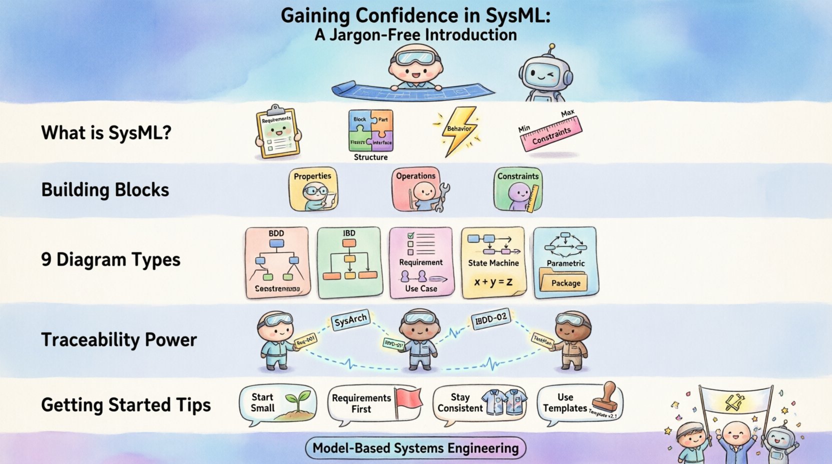
- Requirements: What the system must do.
- Structure: How the system is built (hardware, software, people).
- Behavior: How the system acts over time.
- Constraints: Physical limits like weight, power, or cost.
When you use SysML, you create models rather than just documents. Models are dynamic. They allow you to simulate scenarios and check for inconsistencies before physical prototypes are ever built. This shift from static documentation to dynamic modeling is the heart of Model-Based Systems Engineering (MBSE).
🏗️ The Building Blocks of SysML
Before diving into diagrams, we must understand the vocabulary. SysML relies on a few fundamental concepts to construct a model. These concepts form the grammar of the language.
1. Blocks
A Block is the primary unit of structure. It represents a physical or logical component of a system. Think of a block as a box that contains everything about a specific item. This could be a physical part like an engine, a software module, or even a process like quality assurance.
Key characteristics of a Block include:
- Properties: The parts that make up the block.
- Operations: The functions or actions the block can perform.
- Constraints: The rules the block must follow.
2. Relationships
Blocks do not exist in isolation. They relate to one another. SysML defines specific types of relationships to describe these connections:
- Association: A simple connection between two blocks, like a link or a cable.
- Composition: A strong “whole-part” relationship. If the whole is destroyed, the parts are destroyed.
- Aggregation: A weaker “whole-part” relationship. Parts can exist independently of the whole.
- Generalization: The concept of inheritance. A specific type of block inherits properties from a more general type.
3. Requirements
Every system starts with a need. Requirements capture these needs in a structured format. In SysML, requirements are first-class citizens. You can link them directly to the blocks that fulfill them. This ensures that every design decision can be traced back to a specific need.
📊 The 9 Diagram Types Explained
SysML is famous for its diagram types. There are nine distinct types used to visualize different aspects of a system. Understanding which diagram to use when is crucial for effective modeling. Below is a structured overview of each type.
| Diagram Type | Focus Area | Primary Use Case |
|---|---|---|
| Block Definition Diagram (BDD) | Structure | Defining the hierarchy and composition of system components. |
| Internal Block Diagram (IBD) | Structure | Showing the internal connections and interfaces within a block. |
| Requirement Diagram | Requirements | Managing requirements and their traceability to other model elements. |
| Use Case Diagram | Behavior | Describing high-level interactions between actors and the system. |
| Sequence Diagram | Behavior | Visualizing the flow of messages over time between objects. |
| State Machine Diagram | Behavior | Modeling the different states of a component and transitions between them. |
| Activity Diagram | Behavior | Describing the flow of control and data through a process. |
| Parametric Diagram | Constraints | Defining mathematical constraints and equations for performance analysis. |
| Package Diagram | Organization | Organizing model elements into groups to manage complexity. |
Deep Dive: Structure Diagrams
Structure is the skeleton of your system. The Block Definition Diagram (BDD) is your primary tool here. It shows the top-level hierarchy. You can see how major subsystems relate to the main system. For example, in an aerospace context, a BDD might show the relationship between the Fuselage, Wings, and Engines.
The Internal Block Diagram (IBD) goes deeper. Once you have defined a block in a BDD, you use the IBD to see what is inside. It shows the ports and connectors. Think of it as a blueprint for the internal wiring and data flow. This is essential for understanding how data moves from one sensor to a processor.
Deep Dive: Behavior Diagrams
Behavior describes what the system does. The Use Case Diagram provides a high-level view. It identifies who or what interacts with the system (actors) and what they want to achieve (use cases). It does not show how the system works internally, only the external interactions.
For detailed logic, the State Machine Diagram is powerful. Many systems operate based on conditions. A system might be in a “Standby” state, a “Running” state, or an “Error” state. Transitions occur when specific events happen. This is vital for embedded systems and control logic.
The Activity Diagram is similar to a flowchart. It is best used for processes that involve multiple steps or parallel flows. For instance, a manufacturing process might involve assembly, testing, and packaging happening simultaneously. The Activity Diagram captures this concurrency.
Deep Dive: Constraints and Requirements
The Requirement Diagram links needs to solutions. It allows you to create relationships like “satisfies,” “refines,” or “derives.” If a requirement states “The system must operate in cold temperatures,” you can link this to a specific component, like a battery, that must meet a thermal constraint.
The Parametric Diagram is unique to SysML. It handles math. You can define equations here. For example, you might define the relationship between Velocity, Acceleration, and Time. This allows for performance analysis directly within the model. You can simulate the system to see if it meets its performance goals before building it.
🔗 The Power of Traceability
One of the most significant advantages of SysML is traceability. In traditional document-based engineering, requirements often get lost in translation. A requirement in a Word document might be implemented by code in a file, with no link between them. If a requirement changes, finding the code is a manual nightmare.
In a SysML model, traceability is automatic. You can click on a requirement and see exactly which blocks, diagrams, or constraints fulfill it. This creates a clear audit trail. If a stakeholder asks, “Why did we choose this specific sensor?” you can trace the answer back to the original requirement.
Key benefits of traceability include:
- Impact Analysis: When a requirement changes, you instantly see what parts of the design are affected.
- Verification: You can ensure every requirement has a corresponding design element.
- Validation: You can confirm that the final system meets the original needs.
🛠️ Starting Your Modeling Journey
Transitioning to a modeling workflow takes discipline. It is not enough to just draw diagrams; you must think in models. Here are practical steps to build confidence in this approach.
1. Start Small
Do not attempt to model the entire system on day one. Pick a subsystem. Maybe it is a specific control loop or a simple mechanical assembly. Model just that part. Get comfortable with the relationships and the diagram types. Once you understand the flow, expand outward.
2. Focus on Requirements First
Before drawing blocks, write your requirements. Use the Requirement Diagram to organize them. Group them logically. This ensures that your design has a purpose. A block without a requirement is just noise in the model.
3. Keep it Consistent
Consistency is key to readability. Adopt a naming convention early. Decide how you name blocks, ports, and operations. If you use “Sensor_A” in one diagram, do not use “Sens_1” in another. Consistency reduces cognitive load for anyone reading the model.
4. Leverage Templates
Most modeling environments provide templates. Use them. A template ensures that your diagrams follow the standard. It prevents you from creating non-standard elements that confuse other team members. Standardization allows for better collaboration.
⚠️ Common Pitfalls to Avoid
Even experienced engineers can stumble when working with models. Being aware of common mistakes can save you time and frustration.
- Over-Modeling: Trying to model every single detail is counterproductive. Focus on the important aspects that drive design decisions. If a detail does not impact the system behavior or requirements, leave it out.
- Ignoring Semantics: Drawing a line between two blocks does not mean they are connected. You must define the type of relationship. Is it a data flow? A physical link? An association? The meaning matters.
- Lack of Context: A diagram without a legend or description is confusing. Always add notes or descriptions to explain complex flows. Assume the reader knows nothing about the specific project.
- Static Thinking: SysML is dynamic. Do not treat the model as a static picture. Update it as the design evolves. A model that is not updated becomes a historical document, not a living tool.
🔄 Integration with Real-World Systems
How does this language connect to the physical world? SysML acts as the bridge between abstract requirements and concrete implementation. In modern engineering, this bridge is often crossed using automated tools.
Once the model is stable, the information within it can be used to generate:
- Code Stubs: Software developers can use the model to generate skeleton code.
- Documentation: Reports can be automatically generated from the model elements.
- Test Cases: Test engineers can derive test scenarios from the requirements and behavior diagrams.
- Hardware Specs: Mechanical engineers can extract mass, volume, and interface data.
This integration reduces the gap between design and execution. It ensures that the final product matches the vision. It also allows for simulation. You can run simulations on the parametric diagrams to predict performance.
📚 Continuous Learning and Improvement
Systems engineering is a field that evolves constantly. New standards emerge, and best practices shift. To maintain confidence in your modeling skills, you must commit to continuous learning.
Engage with the community. There are forums and working groups dedicated to SysML. Reading case studies helps you see how others solve problems. You might find a pattern that works better for your specific domain.
Review your own models regularly. Ask yourself: “If I came back to this in six months, would I understand it?” If the answer is no, refactor it. Clarity should always be the priority.
🎯 Final Considerations
Adopting SysML is a journey, not a destination. It requires a shift in mindset from documentation to modeling. However, the benefits are substantial. You gain a clearer understanding of your system, better traceability, and reduced risk of errors.
Remember that the goal is not to create complex diagrams for the sake of complexity. The goal is to solve problems. If a model helps you make a better decision, it has served its purpose. If it becomes a burden, simplify it.
Start with the basics. Understand the blocks. Master the relationships. Learn the diagrams. With practice, the jargon will fade, and you will see the system clearly. This clarity is the true power of Systems Modeling Language. It empowers you to build better systems, faster and with greater confidence.
As you move forward, keep the user in mind. Your model is a communication tool. It is for you, your team, and your stakeholders. Make it useful. Make it clear. Make it valuable.