


Systems engineering is the backbone of complex technology, yet the language used to describe these systems has often been a barrier to entry. SysML, or the Systems Modeling Language, bridges the gap between abstract requirements and concrete design. This guide provides a structured path to understanding SysML, designed for individuals starting from zero experience. We will explore the core concepts, diagram types, and modeling practices without relying on specific software tools.
🧠 What is SysML?
SysML is a general-purpose modeling language for systems engineering applications. It is derived from UML (Unified Modeling Language) but is tailored specifically for systems engineering needs. While UML focuses heavily on software, SysML expands to cover hardware, software, information, people, and processes.
Understanding SysML allows engineers to:
- Visualize complex system architectures 🏗️
- Define and trace requirements clearly 📝
- Analyze system behavior over time ⏱️
- Model performance and physical constraints 📏
The language is standardized by the Object Management Group (OMG), ensuring that models created by one team can be understood by another, regardless of the specific modeling tool used.
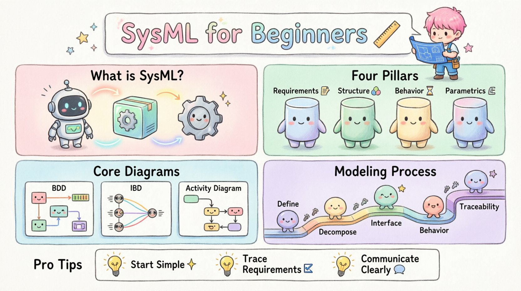
📊 The Four Pillars of SysML
SysML organizes its diagrams into four main categories. Each category serves a specific purpose in the systems engineering lifecycle. Understanding these categories is the first step toward proficiency.
1. Requirement Diagrams
These diagrams define what the system must do. They are not about how the system works, but rather what constraints it must satisfy. Requirements can be traced to other model elements, ensuring that every design decision meets an initial need.
- Requirement Specification: The container for text-based requirements.
- Requirement Satisfaction: Links showing how a design element fulfills a requirement.
- Requirement Verification: Links showing how a test or analysis proves a requirement.
2. Structural Diagrams
Structural diagrams describe the static organization of the system. They show the parts that make up the system and how they connect.
- Block Definition Diagram (BDD): Defines the system hierarchy, properties, and operations.
- Internal Block Diagram (IBD): Shows the internal structure of a block, including connectors and ports.
3. Behavioral Diagrams
Behavioral diagrams describe how the system acts over time. They capture the dynamic aspects of the system.
- Use Case Diagram: High-level interactions between actors and the system.
- Activity Diagram: Detailed workflows and decision points.
- Sequence Diagram: Time-ordered interactions between objects.
- State Machine Diagram: The states of an object and transitions triggered by events.
4. Parametric Diagrams
Parametric diagrams are unique to SysML. They allow for the modeling of mathematical constraints and equations that govern system performance.
- Constraint Blocks: Define equations and variables.
- Constraint Satisfaction: Links equations to model elements.
🛠️ Deep Dive into Core Diagrams
To truly learn SysML, one must move beyond definitions and understand how to construct these diagrams. Below is a detailed breakdown of the most frequently used diagrams.
Block Definition Diagram (BDD)
The BDD is the map of your system. It starts with the top-level system and breaks it down into subsystems and components. This is often called a “decomposition”.
- Blocks: Represent the components. They can be physical parts, logical functions, or organizational entities.
- Relationships: Define how blocks relate to each other. Common relationships include:
- Composition: A whole-part relationship where the part cannot exist without the whole.
- Association: A structural link between blocks, often representing a flow of data or material.
- Generalization: An inheritance relationship, like “Car is a type of Vehicle”.
Internal Block Diagram (IBD)
Once you have defined what the blocks are in a BDD, the IBD explains how they talk to each other inside a specific context. Imagine opening up the top-level block and seeing the wiring inside.
- Ports: Entry and exit points for interaction. You can have flow ports for data, signals, or physical quantities.
- Connectors: Lines that link ports together, defining the path of information or energy.
- References: Links to other blocks defined in the BDD.
Activity Diagram
Activity diagrams are essentially flowcharts adapted for systems engineering. They are excellent for describing complex processes, control flows, and object flows.
- Nodes: Represent actions or steps in a process.
- Transitions: Arrows that dictate the order of execution.
- Swimlanes: Organize activities by the actor or subsystem responsible for them.
📋 Diagram Comparison Table
Choosing the right diagram can be confusing. Use this table to determine which view best suits your current modeling task.
| Diagram Type | Primary Purpose | Best Used For |
|---|---|---|
| Block Definition Diagram (BDD) | System Hierarchy | Defining components and their relationships |
| Internal Block Diagram (IBD) | Internal Connectivity | Showing data flow and interfaces between parts |
| Use Case Diagram | Functional Scope | Identifying user interactions and system boundaries |
| Sequence Diagram | Interaction Timing | Detailing the order of messages between objects |
| State Machine Diagram | Object Lifecycle | Modeling complex state changes and event handling |
| Parametric Diagram | Performance Analysis | Applying mathematical constraints to design variables |
🔄 The Modeling Process
Creating a SysML model is not just about drawing boxes. It is a logical process that follows the systems engineering lifecycle. Following a structured approach ensures consistency and clarity.
Phase 1: Definition
Start by identifying the system boundary. What is inside the system, and what is outside? Define the context diagram to show the external environment. This sets the stage for all subsequent modeling.
Phase 2: Decomposition
Break the system down. Create a Block Definition Diagram. Start with the top-level block and define the major subsystems. Do not worry about details yet; focus on the hierarchy. Ensure each block has a clear purpose.
Phase 3: Interface Definition
Define how the subsystems connect. Use Internal Block Diagrams to map out the connections. Define the types of data or materials that flow across these connections. This prevents ambiguity later when implementation begins.
Phase 4: Behavior Specification
Describe what the system does. Use Activity Diagrams for high-level workflows and State Machine Diagrams for complex logic. Ensure that the behaviors align with the structural components defined earlier.
Phase 5: Requirement Traceability
Link everything back to the initial requirements. Every design decision should be traceable to a specific requirement. This is critical for verification and validation later in the project.
🚧 Common Pitfalls to Avoid
Even experienced engineers make mistakes when modeling. Being aware of common pitfalls can save significant time during the review process.
- Over-Modeling: Trying to model every detail at the start. Start with the big picture and refine as needed. Not every aspect of a system needs a diagram.
- Ignoring Interfaces: Defining blocks without defining how they connect. A system is defined by its interfaces, not just its parts.
- Inconsistent Naming: Using different names for the same concept. Establish a naming convention early and stick to it.
- Skipping Requirements: Focusing on design without linking to requirements. This makes verification impossible.
- Mixing Levels of Abstraction: Combining high-level strategy with low-level implementation details in the same diagram. Keep diagrams focused.
📈 Integrating Requirements and Design
One of the strongest features of SysML is the ability to link requirements directly to design elements. This creates a living document that evolves with the project.
Traceability Matrix
A traceability matrix is a view that shows the relationships between requirements and other model elements. It helps answer questions like:
- Which requirements have not been satisfied yet? ❌
- Which requirements are no longer relevant? 🗑️
- Has a specific design element been tested against its requirement? ✅
Verification and Validation
Verification asks, “Did we build the system right?” Validation asks, “Did we build the right system?” SysML supports both.
- Verification: Uses analysis models and test cases linked to requirements.
- Validation: Uses simulations and user feedback linked to use cases.
🎓 Developing Your Skills
Learning SysML is a journey. It requires practice and patience. Here are some strategies to improve your modeling skills without relying on paid courses or specific tools.
Practice with Paper
Before using any digital environment, try sketching diagrams on paper. This helps you focus on the logic and relationships rather than the aesthetics or tool features.
Study Existing Models
Look for open-source modeling examples or case studies. Analyze how others have structured their systems. Identify patterns in their use of diagrams.
Join Communities
Engage with the systems engineering community. Forums and discussion groups are excellent places to ask questions about specific modeling challenges.
Iterate
Your first model will not be perfect. Expect to refactor your diagrams as you learn more about the system. This is a normal part of the engineering process.
🔗 Connecting SysML to Other Standards
SysML does not exist in a vacuum. It often integrates with other standards and methodologies.
ISO/IEC 15288
This is the international standard for system life cycle processes. SysML models can be used to support the documentation and analysis requirements of ISO/IEC 15288.
MBSE (Model-Based Systems Engineering)
SysML is the primary language for MBSE. MBSE is the practice of using models as the primary source of truth, rather than documents. Adopting SysML is a key step in transitioning to an MBSE environment.
🔍 Summary of Key Concepts
To recap, here are the essential takeaways for anyone beginning their SysML journey:
- Focus on Communication: Models are for communication between stakeholders, not just for the engineer.
- Structure and Behavior: Distinguish between what the system is (Structure) and what it does (Behavior).
- Requirements First: Always start with the requirements to guide your design.
- Keep it Simple: Use the simplest diagram that conveys the necessary information.
- Traceability: Ensure every design element links back to a requirement.
🌟 Moving Forward
Systems engineering is evolving. The shift from document-based to model-based approaches is changing how complex systems are designed and built. By learning SysML, you are equipping yourself with a skill set that is increasingly in demand across industries like aerospace, automotive, and defense.
Start small. Pick a simple system you understand well and try to model it. Apply the principles of decomposition, interface definition, and requirement tracing. As you gain confidence, you can tackle more complex architectures.
Remember, the goal of modeling is clarity. If your model is confusing to others, it is not effective. Use the diagrams to facilitate discussion, uncover issues early, and ensure that the final system meets its intended goals.
📝 Final Checklist for New Modelers
| Task | Status |
|---|---|
| Identify system boundary | ⬜ |
| Define top-level blocks | ⬜ |
| Map internal interfaces | ⬜ |
| Link requirements to design | ⬜ |
| Verify traceability | ⬜ |
Consistency is the key to success in systems modeling. By adhering to these principles, you can build robust models that stand the test of time and change.