


System engineering relies heavily on the ability to communicate complex structures without ambiguity. When a model grows beyond a simple sketch, chaos becomes a significant risk. A disorganized SysML model creates friction, slows down analysis, and obscures critical design decisions. The difference between a model that drives innovation and one that hinders progress often lies in its architecture.
This guide explores the structural principles required to build a robust SysML environment. We will examine how to structure packages for logical flow, manage views for specific stakeholder needs, and maintain clarity throughout the lifecycle. By establishing a disciplined approach to organization, you ensure that the model remains a reliable source of truth rather than a static artifact.
1. The Foundation of Structure 🏛️
Before drawing a single block or defining a requirement, the skeleton of the model must be defined. SysML provides a namespace mechanism through packages, which serve as containers for model elements. Think of packages not merely as folders, but as logical domains that group related concepts.
Without a clear hierarchy, elements become scattered, making traceability difficult. A well-defined structure supports:
- Scalability: Adding new subsystems does not disrupt existing definitions.
- Navigation: Engineers can locate elements without searching through a flat list.
- Reusability: Standard subsystems can be imported and referenced across multiple projects.
- Ownership: Different teams can own specific packages, reducing merge conflicts.
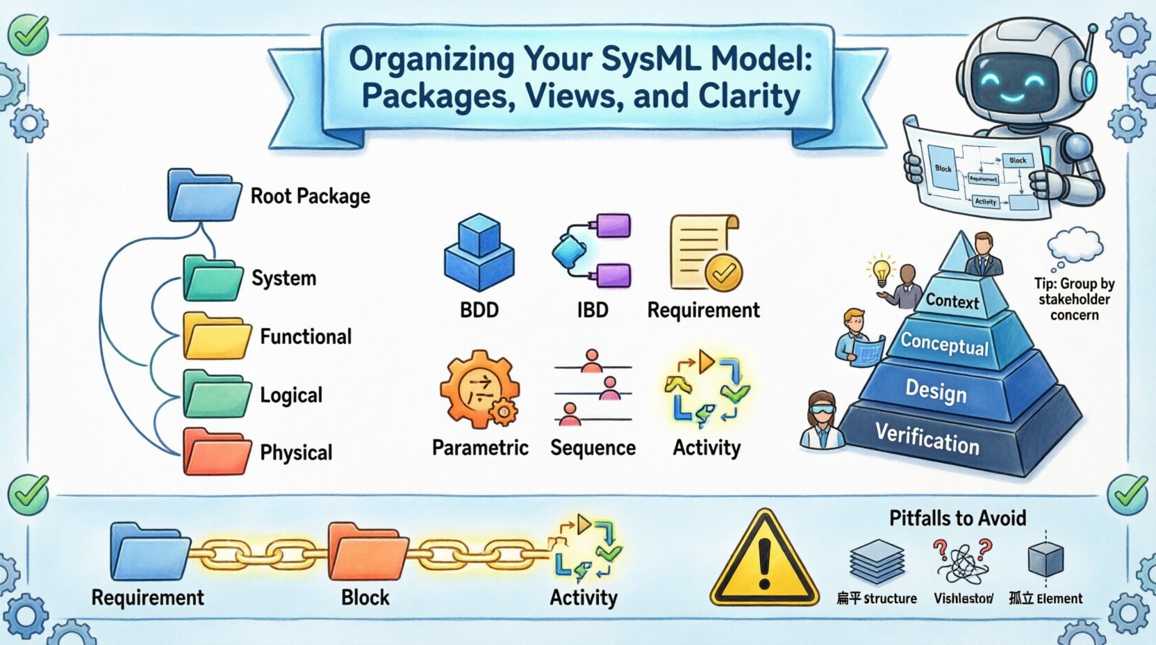
Root Package Strategy
Every model begins with a root package. This should represent the entire system or project. Avoid placing high-level definitions directly in the root. Instead, create a first-level package for the top-level system. This keeps the root clean and allows for better version control at the project level.
Decomposition Approaches
There are multiple ways to structure a package hierarchy. The choice depends on the nature of the system and the engineering methodology.
- Functional Decomposition: Packages represent functions or processes (e.g., “Power Management”, “Navigation”). This is useful for understanding what the system must do.
- Logical Decomposition: Packages represent logical components that may not be physical (e.g., “Software Core”, “Data Link”). This bridges the gap between function and implementation.
- Physical Decomposition: Packages represent physical boundaries or hardware (e.g., “Chassis”, “Sensor Array”). This is critical for manufacturing and integration.
- Hybrid Approach: Many complex systems require a combination of the above. A top-level package might split into functional and physical sub-packages.
2. Designing Robust Package Hierarchies 📦
Once the decomposition strategy is selected, the implementation requires attention to naming and relationships. Poor naming conventions are the leading cause of confusion in large models. Names should be unique, descriptive, and consistent.
Naming Conventions
Adopt a standard naming convention early in the project. This applies to packages, blocks, requirements, and diagrams. Inconsistency leads to ambiguity.
- CamelCase: Use
SystemFunctionorsystem_functionfor packages. - Prefixing: Use prefixes for specific types, such as
REQ_for requirements orBLK_for blocks. - Versioning: Include version numbers in package names only if the package itself is versioned, not for every iteration.
- Context: Ensure the package name implies its context (e.g., “TopLevel” vs. “SubsystemA”).
Avoiding Circular Dependencies
A common structural error is creating circular dependencies between packages. This occurs when Package A imports Package B, and Package B imports Package A. This creates a logical loop that can break dependency resolution and compilation.
To prevent this:
- Define Imports Explicitly: Only import elements that are strictly necessary.
- Use Interfaces: Define interfaces in a neutral package and import them into functional packages.
- Review Topology: Periodically map the dependency graph to ensure a directed acyclic graph (DAG) structure.
Package vs. Viewpoint
Do not confuse packages with viewpoints. Packages organize elements. Viewpoints organize how those elements are presented. A package might contain multiple views, but a view does not contain a package.
3. Managing Views for Effective Communication 📊
Models contain vast amounts of data. Not every stakeholder needs to see every detail. Views allow you to filter the model to show specific aspects relevant to a specific audience. Organizing these views is as critical as organizing the model elements themselves.
Diagram Types and Purpose
Each SysML diagram type serves a specific purpose. Misusing a diagram type leads to confusion. Group your diagrams logically within packages.
- Block Definition Diagram (BDD): Defines the static structure. Use this for defining blocks, interfaces, and relationships.
- Internal Block Diagram (IBD): Defines the internal structure. Use this for showing ports, flows, and connectors within a block.
- Requirement Diagram: Defines requirements and their relationships. Group all requirements in a dedicated package.
- Parametric Diagram: Defines constraints and equations. Keep these isolated to avoid cluttering structural views.
- Sequence Diagram: Defines dynamic behavior. Use this for interaction flows between blocks.
- Activity Diagram: Defines logic and flow. Use this for algorithmic behavior or mission profiles.
Abstraction Levels
Organize views based on abstraction levels. A single subsystem should have views at different levels of detail.
- Context View: Shows the system in relation to its environment. Minimal internal detail.
- Conceptual View: Shows the internal logic without physical implementation details.
- Design View: Shows the detailed implementation, including interfaces and connections.
- Verification View: Shows how requirements are linked to specific design elements.
Diagram Management
Keep diagram names meaningful. Avoid names like “Diagram1” or “Untitled”. Use descriptive titles that explain the content, such as “Power System Interface”.
When a diagram becomes too crowded, split it. A single view with too many elements loses its communicative power. Create a master view for overview and detail views for specific subsystems.
4. Establishing Clarity Standards 🎯
Clarity is not accidental. It is the result of deliberate standardization. When multiple engineers contribute to a model, consistency is the primary requirement for maintainability.
Consistency in Notation
Ensure all users follow the same modeling standards. This includes:
- Block Shapes: Define standard shapes for specific block types (e.g., hardware vs. software).
- Color Coding: While CSS styling is often disabled in export, using color to denote status (e.g., “In Progress” vs. “Approved”) within the tool environment helps visual scanning.
- Iconography: Use standard icons for interfaces (lollipop) and connectors (flow lines).
- Text Formatting: Use bold text for critical constraints and normal text for descriptions.
Documentation Within the Model
Do not rely solely on external documents. SysML is designed to integrate documentation. Use text blocks or notes attached to model elements.
- Notes: Attach explanatory text to specific blocks or requirements.
- Constraints: Use constraint blocks for mathematical or logical rules.
- Property Values: Define properties for blocks to store metadata (e.g., weight, volume, cost).
Standardizing Views Table
Below is a recommended structure for organizing views within a package hierarchy.
| Package Name | View Type | Target Audience | Detail Level |
|---|---|---|---|
| SystemOverview | BDD | Management | High |
| SubsystemA | IBD | Engineers | Medium |
| SubsystemA | Requirement | QA | High |
| SubsystemA | Parametric | Analysts | Very High |
5. Traceability and Verification 🔗
The true value of a SysML model lies in its ability to trace requirements to design and verify performance. Organization plays a pivotal role here. If elements are scattered, traceability links become broken or lost.
Requirement Traceability
Requirements must be linked to the elements that satisfy them. This creates a bidirectional flow of information.
- Verification Link: Connects a requirement to a test case or analysis.
- Derivation Link: Shows how a requirement was derived from a higher-level requirement.
- Satisfaction Link: Shows which block or interface satisfies a requirement.
To maintain this:
- Centralize Requirements: Keep all requirements in a dedicated package, even if they reference elements elsewhere.
- Link from Source: Always link from the requirement to the design, not just the design to the requirement.
- Review Links: Periodically run traceability matrices to ensure all links are intact.
Verification Matrices
Generate verification matrices to ensure coverage. A verification matrix is a view that lists requirements in one column and the corresponding design elements in another. This is a critical artifact for certification and compliance.
Ensure that every requirement has at least one satisfied link. Every requirement without a link is a risk. Every design element without a requirement is a potential scope creep.
6. Maintenance and Long-term Evolution 🔄
Models are living documents. They evolve as the system design changes. A rigid structure breaks under change, while a flexible structure adapts. The goal is to minimize the impact of changes.
Change Management
When a change occurs, it should propagate through the model without breaking links.
- Impact Analysis: Before changing a block, check which requirements and diagrams reference it.
- Version Control: Use version control systems to manage model files. This allows you to revert changes if necessary.
- Release Notes: Document major changes in the model package properties or associated text blocks.
Library Management
Use libraries for reusable elements. If you have standard components (e.g., a standard sensor or a standard connector), define them in a library package and import them where needed.
- Standardization: This ensures that all engineers use the same definition for common parts.
- Updates: If a standard part changes, you update the library, and the change propagates to all imported models.
- Isolation: Libraries should not contain project-specific logic. Keep them generic.
Archiving and Deprecation
Do not delete old elements. Instead, mark them as deprecated or obsolete. This preserves the history of the design evolution.
- Status Property: Add a property to blocks to indicate status (e.g., “Active”, “Deprecated”).
- Archive Package: Move old versions to an “Archive” package to keep the main model clean.
- Reference Preservation: Maintain links to archived elements so the history of why a decision was made is not lost.
7. Common Pitfalls to Avoid ⚠️
Even experienced engineers fall into traps when organizing models. Awareness of these pitfalls helps prevent structural debt.
- Flat Structure: Placing everything in the root package. This makes navigation impossible as the model grows.
- Over-Abstraction: Creating too many levels of packages. This makes the model deep and hard to reach specific elements.
- Diagram Clutter: Putting too many elements on a single diagram. This reduces readability and makes updates painful.
- Orphaned Elements: Creating elements that are not referenced by anything. These add noise and maintenance overhead.
- Inconsistent Naming: Using “Block1” and “SystemBlock” interchangeably. This confuses search and traceability.
- Ignoring Constraints: Failing to define constraints early leads to late-stage validation failures.
8. The Role of Metadata 📝
Beyond structure and views, metadata adds context. Properties attached to elements allow for filtering and reporting.
Custom Properties
Define properties for blocks that are relevant to your domain. For example, a “Weight” property on a hardware block or a “Cost” property on a subsystem.
- Searchability: Metadata allows you to search for all blocks with a specific weight range.
- Reporting: Export these properties to generate cost or mass reports automatically.
- Filtering: Filter views based on metadata (e.g., show only blocks with “Status = Approved”).
Tags
Tags provide a lightweight way to categorize elements without creating new properties. Use tags for classification, such as “SafetyCritical” or “ExternalInterface”.
Conclusion on Model Health 🌟
A well-organized SysML model is a strategic asset. It reduces the time required for analysis, improves communication between teams, and lowers the risk of integration errors. The effort invested in establishing packages, views, and clarity standards pays dividends throughout the entire system lifecycle.
By following these structural principles, you create an environment where the model serves the engineer, rather than the engineer serving the model. This shift in dynamic is essential for modern systems engineering. Prioritize structure, maintain consistency, and ensure traceability. These practices form the bedrock of a successful modeling initiative.
Remember that organization is not a one-time task. It requires ongoing maintenance and discipline. Regularly audit your package structure and review your views to ensure they still meet stakeholder needs. As the system evolves, your model must evolve with it, maintaining its clarity and utility at every stage.
Ultimately, the goal is a model that is easy to understand, easy to modify, and easy to verify. This is the standard for high-quality systems engineering. Commit to these practices, and your models will reflect the complexity of the systems they describe without succumbing to chaos.