


Systems engineering relies heavily on the ability to describe not just what a system is, but how it behaves over time. Static structures, such as block diagrams, define the components and their relationships. However, dynamic behavior requires a different approach. SysML State Machines provide the necessary framework to model this dynamic nature. This guide explores the mechanics of creating robust state machine diagrams, ensuring your system design accurately reflects real-world operational logic. We will examine the core components, the flow of execution, and the strategies for handling complexity without introducing unnecessary confusion.
Understanding the Core Purpose 🏗️
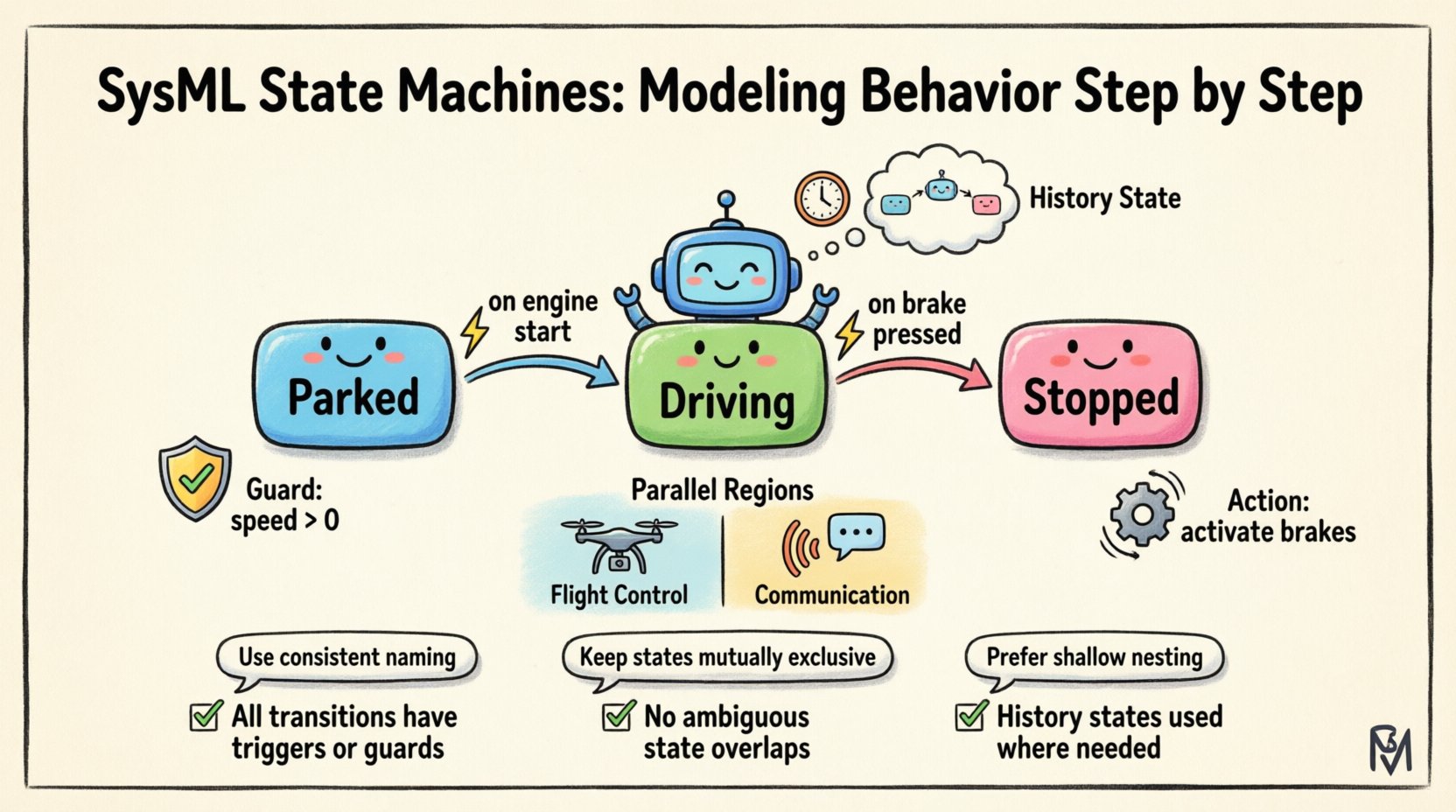
A state machine diagram describes the possible states of an object and the events that cause transitions between those states. Unlike a flowchart, which depicts a process flow, a state machine tracks the condition of an entity. This distinction is critical for systems where the current context dictates future actions. For example, an autonomous vehicle must behave differently depending on whether it is in a “parked” state or a “driving” state.
When constructing these models, the goal is clarity. A well-designed state machine eliminates ambiguity about how a system reacts to inputs. It defines the lifecycle of an object from creation to termination. This lifecycle management is essential for verifying that all operational scenarios are covered. Without this, gaps in logic can lead to system failures during deployment.
Why State Machines Matter
Clarity: Visual representation reduces cognitive load when analyzing complex logic.
Verification: Enables simulation and checking of all possible paths.
Documentation: Serves as a single source of truth for developers and engineers.
Consistency: Ensures that behavior rules are applied uniformly across the system.
Defining the Fundamental Elements ⚙️
To build a state machine, you must understand the atomic building blocks. Each element serves a specific function in the logic flow. Misusing these elements can lead to models that are difficult to maintain or interpret.
States
States represent a condition or situation during which an object satisfies some condition, performs some activity, or waits for some event. They are the nodes of the graph. States can be simple or composite.
Simple State: A state with no internal structure.
Composite State: A state that contains its own internal state machine. This allows for nesting, managing complexity by breaking down large behaviors into manageable sub-behaviors.
Final State: Marks the end of a lifecycle. There can be multiple final states, but each transition path should ideally lead to one.
Transitions
Transitions connect states. They represent the movement from one condition to another. A transition is triggered by an event, provided any associated guard conditions are met. Once the transition occurs, the actions defined on the transition are executed.
Events
Events are the triggers that cause transitions. They can be signal events, call events, change events, or time events. An event does not execute logic on its own; it initiates the transition process.
Constructing the Logic Flow 🛣️
Building the behavior model involves connecting states with transitions. This section details the specific attributes that control how a transition executes.
Triggers and Guards
A transition typically includes a trigger. This is the event that wakes the system up to consider moving. However, moving is not always the correct response. Guard conditions act as filters. A guard is a boolean expression that must evaluate to true for the transition to fire.
Element | Function | Example |
|---|---|---|
Trigger | Initiates the transition | Button Pressed |
Guard | Validates conditions | [battery_level > 20%] |
Action | Executes during transition | log_entry() |
Consider a scenario where a system enters a “Maintenance Mode”. The trigger might be a command from an operator. However, the guard condition might require that the system is not currently active in a critical task. This separation of trigger and guard ensures robust logic.
Internal Activities
Not all changes require a transition. Sometimes, an event occurs, but the system stays in the same state while performing an action. This is handled by internal activities. Internal activities are processed without exiting the current state, meaning entry and exit actions are not triggered.
Entry Action: Executed immediately upon entering the state.
Exit Action: Executed immediately before leaving the state.
Do Action: An activity performed while in the state. It continues until an event triggers a transition or the activity completes.
Managing Complexity with History 🧠
As systems grow, state machines can become unwieldy. Deep nesting and many transitions create a web that is hard to follow. History states offer a solution to this problem by preserving the state of a composite state.
Shallow vs. Deep History
History states allow a system to remember where it left off. There are two distinct types:
Shallow History: Indicates that the composite state was previously active. It restores the state to the last active sub-state, but only one level deep.
Deep History: Restores the exact state of the composite machine. This includes the last active sub-state and any nested sub-states within it.
Using history states is particularly useful in systems that suspend and resume operations. If a system is paused and later resumed, a deep history state ensures it returns to the exact point of suspension, rather than resetting to the beginning.
Implementation Strategy
When incorporating history, ensure that the entry point of the history state is clear. Ambiguity here can lead to unpredictable behavior during simulation. Always document why a history state is used. Is it for efficiency? Is it for user experience continuity? Clear intent aids future maintainers.
Handling Concurrency with Regions 🌐
Complex systems often operate in multiple modes simultaneously. A single state machine cannot easily represent parallel processes. SysML addresses this through regions.
Parallel Regions
Regions divide a composite state into independent sub-machines. These sub-machines operate concurrently. A transition in one region does not block transitions in another. This is analogous to multi-threading in software engineering.
Partitioning: Split the state machine into logical regions based on independent behaviors.
Independence: Events in one region do not inherently affect others unless explicitly linked.
Synchronization: Use entry and exit points to coordinate between regions when necessary.
Example Scenario
Imagine a drone control system. One region handles “Flight Control”, managing altitude and position. Another region handles “Communication”, managing telemetry and command reception. These operate in parallel. If the communication link is lost, the “Flight Control” region might trigger a “Return to Home” action without stopping the telemetry logging in the communication region.
Connecting Behavior to Structure 🔗
A state machine does not exist in a vacuum. It describes the behavior of a specific block or part. Linking the state machine to the structural diagram is vital for traceability.
State Machine Context
Every state machine must be owned by a context. This context is usually a block or a part. The context defines the scope of the behavior. For example, a “Battery” block might have a state machine describing its charge levels. A “Vehicle” block might have a state machine describing its operational modes.
Ports and Interfaces
Transitions often interact with the external environment. This interaction is managed through ports and interfaces. A state machine can send signals out or receive signals in via these connectors. Defining these interfaces correctly ensures that the behavior model can be integrated into the larger system architecture.
Required Interface: Indicates what the state machine needs from its environment.
Provided Interface: Indicates what the state machine offers to the environment.
Validation and Consistency Checks ✅
Once the model is constructed, it must be validated. A model that looks good visually may still contain logical errors. Validation ensures that the behavior is sound.
Reachability Analysis
Check if every state is reachable from the initial state. Dead states (states that cannot be entered) indicate a modeling error. Conversely, ensure that every state can eventually reach a final state or a stable condition. Infinite loops should be intentional and documented.
Event Coverage
For every state, determine what happens if an unexpected event occurs. If a transition is not defined for a specific event, the system might halt or enter an undefined state. Define default behaviors or exception handling states to manage these scenarios.
Traceability
Link state machine elements to requirements. If a requirement states “The system must shut down if temperature exceeds X”, there should be a corresponding state or transition in the model. This traceability is crucial for certification and compliance processes.
Best Practices for Sustainable Modeling 📝
To maintain the quality of the model over time, adhere to the following practices.
Keep It Simple: Avoid unnecessary nesting. If a composite state becomes too large, consider splitting it into separate state machines.
Use Naming Conventions: Consistent naming for states, events, and actions helps in navigation and searching.
Document Assumptions: Add notes to explain why certain logic exists. Future engineers may not know the original constraints.
Review Regularly: Models evolve as requirements change. Schedule regular reviews to ensure the behavior model matches the current design.
Common Pitfalls to Avoid 🚫
Even experienced engineers can make mistakes. Awareness of common errors helps in prevention.
Confusing Events with Actions: An event triggers a transition. An action is performed. Do not conflate the two.
Ignoring Entry/Exit: Failing to define what happens when entering or leaving a state can lead to resource leaks or inconsistent configurations.
Over-Parallelization: Using too many regions makes the model hard to understand. Only parallelize when behaviors are truly independent.
Missing Guards: Relying solely on triggers can lead to unintended transitions if the guard condition is not explicit.
Summary of Key Concepts 📌
Building effective state machines requires a disciplined approach. You start with the fundamental elements: states, transitions, and events. You then layer in complexity with history states, regions, and internal activities. Throughout the process, you must ensure that the behavior aligns with the structural components of the system. Validation is not optional; it is a necessary step to ensure reliability.
By following these guidelines, you create a model that serves as a reliable blueprint for development and testing. The state machine becomes a communication tool, bridging the gap between high-level requirements and low-level implementation. It captures the dynamic essence of the system, ensuring that behavior changes are modeled accurately and consistently.
Remember that the goal is not complexity for its own sake. The goal is clarity. A simple, well-structured state machine is more valuable than a complex one that is difficult to understand. Focus on the logic, document the intent, and verify the paths. This approach leads to robust systems that perform as expected in the field.