


Engineering education often bridges the gap between theoretical knowledge and practical application. As you progress through your degree, you will encounter complex system designs that require more than just code or circuit diagrams. This is where Systems Modeling Language (SysML) becomes essential. SysML provides a standardized way to describe, analyze, design, and verify systems. For university students, adopting this language early in your academic career can significantly improve the clarity, traceability, and success of your capstone projects.
This guide serves as a comprehensive reference. It covers the core components of SysML, explains how to apply them to academic work, and highlights best practices for documentation. Whether you are designing a robotics platform, a software architecture, or a mechanical assembly, SysML offers a structured approach to system engineering.
Understanding Systems Modeling Language 🧩
SysML is a general-purpose modeling language. It is an extension of the Unified Modeling Language (UML), adapted specifically for systems engineering. While UML focuses heavily on software and object-oriented design, SysML expands the scope to include hardware, software, information, personnel, and procedures. In an academic setting, this versatility is crucial because university projects often involve multidisciplinary teams.
When you use SysML, you are creating a visual representation of a system. These models act as a common language for stakeholders. They allow you to visualize complex relationships that might otherwise be lost in text-heavy documentation. The language is based on diagrams. Each diagram type serves a specific purpose, capturing different aspects of the system lifecycle.
Adopting this standard early helps you develop systems thinking. It forces you to define requirements clearly before jumping into implementation. This discipline reduces errors later in the development process and ensures that the final product meets the initial intent.
Why Students Should Adopt SysML 📈
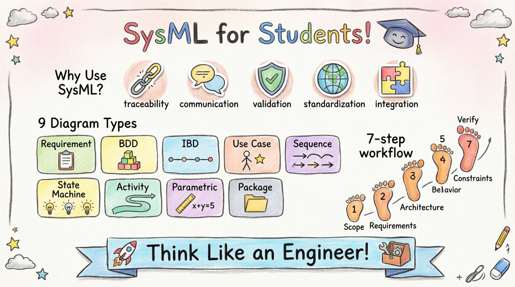
Many students wonder if the time investment required to learn a new modeling language is worth it. The answer lies in the clarity and structure it brings to complex projects. Here are several reasons why SysML is beneficial for university-level work:
- Traceability: You can link requirements directly to design elements. If a requirement changes, you can instantly see which parts of the model are affected.
- Communication: Visual models are easier for professors and industry partners to understand than dense text reports. They provide a high-level overview of the architecture.
- Validation: You can verify that your system design actually satisfies the constraints and goals defined at the start of the project.
- Standardization: SysML is an international standard (ISO/IEC 19500). Using it demonstrates professional competence to future employers.
- Integration: It helps integrate mechanical, electrical, and software components into a cohesive whole, which is common in modern engineering projects.
By using SysML, you move beyond ad-hoc sketching. You create a documented artifact that can be reviewed, modified, and reused. This is particularly valuable for semester-long projects where documentation is a significant part of the grading criteria.
Core Diagrams and Their Applications 📊
SysML consists of nine distinct diagram types. Not every project will require all of them. Understanding when to use each diagram is a key skill. Below is a breakdown of the primary diagrams and their specific uses in student projects.
| Diagram Type | Primary Focus | Common Use Case |
|---|---|---|
| Requirement Diagram | System Needs | Defining functional and non-functional requirements. |
| Block Definition Diagram (BDD) | Structure | Defining system parts and their relationships. |
| Internal Block Diagram (IBD) | Internal Connections | Showing how parts interact and exchange data. |
| Use Case Diagram | Interaction | Describing how users interact with the system. |
| Sequence Diagram | Behavior | Showing time-ordered interactions between parts. |
| State Machine Diagram | State Logic | Defining how the system reacts to events over time. |
| Activity Diagram | Workflow | Modeling the flow of control or data. |
| Parametric Diagram | Constraints | Mathematical constraints and performance analysis. |
| Package Diagram | Organization | Organizing model elements into groups. |
Deep Dive: Requirement Diagrams 📝
The Requirement Diagram is often the starting point for any engineering project. It captures what the system must do. In a university context, this aligns perfectly with project specifications provided by professors or clients.
Key elements in this diagram include:
- Requirement Blocks: These represent specific needs. For example, “The robot must lift 5kg” or “The software response time must be under 100ms”.
- Constraints: These define limits on requirements. You might specify that a component must operate within a certain temperature range.
- Relationships: SysML allows you to link requirements. You can specify if one requirement satisfies another, or if a requirement is refined into sub-requirements.
Traceability is the most important aspect here. You should link every requirement to a design element. If a requirement is not linked to anything in your model, it is considered “orphaned.” Orphaned requirements indicate incomplete design work. During your project defense, professors will look for these links to verify that you have addressed every specification.
Deep Dive: Structure Diagrams 🧱
Once requirements are defined, you need to define the system structure. SysML offers two main diagrams for this purpose: the Block Definition Diagram (BDD) and the Internal Block Diagram (IBD).
Block Definition Diagram (BDD)
The BDD defines the system hierarchy. It breaks the system down into blocks. A block can represent a physical part, a software module, or a logical function. This diagram is essentially a class diagram adapted for systems.
When creating a BDD for a university project:
- Define the top-level block as your system.
- Create child blocks for subsystems. For a drone project, you might have blocks for “Power System”, “Control Unit”, and “Propulsion”.
- Define interfaces. Interfaces define how blocks communicate without knowing the internal details of the other block.
Internal Block Diagram (IBD)
The IBD zooms in on a specific block to show its internal composition. It reveals how the internal parts connect.
- Ports: These are the connection points on a block. They define where data or signals enter or leave.
- Flows: These represent the movement of data, material, or energy between ports.
- Properties: These define the internal variables or components within the block.
This level of detail is crucial for interdisciplinary projects. It helps mechanical engineers understand where the electrical signals come from, and software engineers understand the physical constraints.
Deep Dive: Behavioral Diagrams ⚙️
Structure defines what the system is. Behavior defines what the system does. SysML provides several diagrams to capture behavior over time.
Use Case Diagram
This diagram focuses on the user perspective. It identifies actors (users or external systems) and the use cases (actions) they perform. It is excellent for defining the scope of your project. If an action is not in a use case, it is likely out of scope.
Sequence Diagram
Sequence diagrams show interactions in chronological order. They are ideal for detailing how a specific function works.
- They show objects (or blocks) as vertical lines.
- Messages are shown as horizontal arrows between the lines.
- You can model feedback loops and error handling.
For a software-heavy project, this diagram helps validate the logic flow before writing code. For hardware projects, it can model signal handshakes between components.
State Machine Diagram
Some systems have distinct states. A traffic light, a payment terminal, or a robotic arm in “Idle” vs “Moving” mode are examples. The State Machine Diagram maps out these states and the transitions between them.
- States: Conditions during which the system performs an action or waits for an event.
- Transitions: The trigger that moves the system from one state to another.
- Events: The triggers that cause the transition.
This is vital for embedded systems and control logic. It prevents race conditions and ensures the system behaves predictably under all conditions.
Deep Dive: Parametric Diagrams 📐
Parametric diagrams are unique to SysML and are highly valued in engineering curricula. They allow you to model constraints and perform analysis.
You can define equations directly in the model. For example, you can link the “Voltage” property of a power block to the “Current” property of a load block using Ohm’s Law. This enables early performance validation.
Benefits include:
- Verification: You can check if design choices meet physical limits.
- Trade-off Analysis: You can adjust parameters to see how they affect overall system performance.
- Documentation: It documents the mathematical basis of your design decisions.
While not every project requires complex math, including parametric constraints shows a high level of engineering rigor.
Building a Model: A Step-by-Step Workflow 🛠️
Creating a SysML model can seem overwhelming. A structured workflow helps manage the complexity. Follow this sequence for your university projects:
- Define Scope: Create a Use Case Diagram to establish boundaries. Identify the main actors and functions.
- Capture Requirements: Build the Requirement Diagram. List all functional and non-functional needs. Ensure they are specific and measurable.
- Develop Architecture: Create the Block Definition Diagram. Break the system into manageable subsystems. Define interfaces between them.
- Detail Internal Structure: Use Internal Block Diagrams to show connections for critical subsystems. Define ports and flows.
- Model Behavior: Use Sequence and State Machine diagrams to describe how the system reacts to inputs and events.
- Apply Constraints: If applicable, add Parametric Diagrams to validate performance metrics.
- Verify Traceability: Check that every requirement is linked to a design element. Ensure no requirements are orphaned.
This iterative process allows you to refine the model as you learn more about the system. Do not try to build the perfect model in one pass. Start with the basics and add detail as needed.
Common Pitfalls to Avoid 🚫
Students often make predictable mistakes when modeling. Being aware of these can save you time during the grading phase.
- Over-Modeling: Trying to model every single detail can clutter the diagram. Focus on high-level architecture first. Only detail what is necessary for clarity.
- Circular References: Ensure your traceability links do not form loops. A requirement should not reference a design element that references back to the same requirement in a circular manner.
- Missing Interfaces: Clearly define how blocks communicate. If a block sends data to another, there must be a defined interface or port.
- Ignoring Constraints: Do not leave performance requirements as text only. If you have numerical constraints, model them in the Parametric Diagram if possible.
- Inconsistent Naming: Use consistent naming conventions throughout the model. A block named “Sensor” should not be referred to as “Data Collector” in another diagram.
Tips for Academic Success 💡
When presenting your SysML models to professors or in a thesis, consider the following:
- Keep it Clean: Avoid crossing lines and cluttered layouts. Use packages to organize complex models into readable sections.
- Add Annotations: Use notes to explain complex decisions. A diagram is a visual aid, but sometimes text is needed for context.
- Export Properly: Many tools allow you to export diagrams to PDF or images. Ensure the resolution is high enough for printed reports.
- Focus on Logic: Professors are less interested in the aesthetics and more interested in the logic. Does the model accurately represent the system?
- Version Control: If you use a tool that supports it, keep track of model versions. This helps document your design evolution.
Integration with Other Engineering Disciplines 🔗
SysML is not just for mechanical or software engineers. It bridges the gap between disciplines. In a multidisciplinary team, the model acts as the single source of truth.
For example, in a mechatronics project:
- The mechanical engineer defines the physical blocks and dimensions in the BDD.
- The electrical engineer defines the power and signal interfaces.
- The software engineer defines the logic using State Machines.
All these views are integrated into one model. This reduces the risk of incompatible designs. It ensures that the software logic matches the electrical signals, which matches the mechanical movement.
Documentation and Reporting 📄
Academic projects require extensive documentation. SysML models can be used directly to generate reports. Many modeling environments allow you to generate documentation that extracts information from the model.
Key sections to include in your report based on the model:
- System Overview: Use the BDD to show the architecture.
- Requirements Analysis: Use the Requirement Diagram to show traceability.
- Functional Design: Use Sequence and Activity diagrams to explain workflows.
- Interface Control: Use IBD to detail connections.
Generating text from the model ensures consistency. If you update the model, the documentation updates too. This reduces the likelihood of your report contradicting your design.
Final Thoughts on Systems Thinking 🌍
Learning SysML is about more than just drawing diagrams. It is about developing a mindset. You learn to think about systems holistically. You consider inputs, outputs, constraints, and interactions. This perspective is highly valued in the industry.
As you work on your university projects, treat the model as a living document. It should evolve as you learn. Do not be afraid to refactor your model. The goal is clarity and understanding, not perfection on the first try. By mastering these modeling techniques, you are preparing yourself for the complexities of modern engineering.
Start small. Define your requirements clearly. Build your structure. Verify your behavior. With practice, SysML will become an indispensable tool in your engineering toolkit. It provides the structure needed to turn complex ideas into functional reality.