
Mastering Multi-Threaded Workflows in VP OpenDocs with Swimlanes
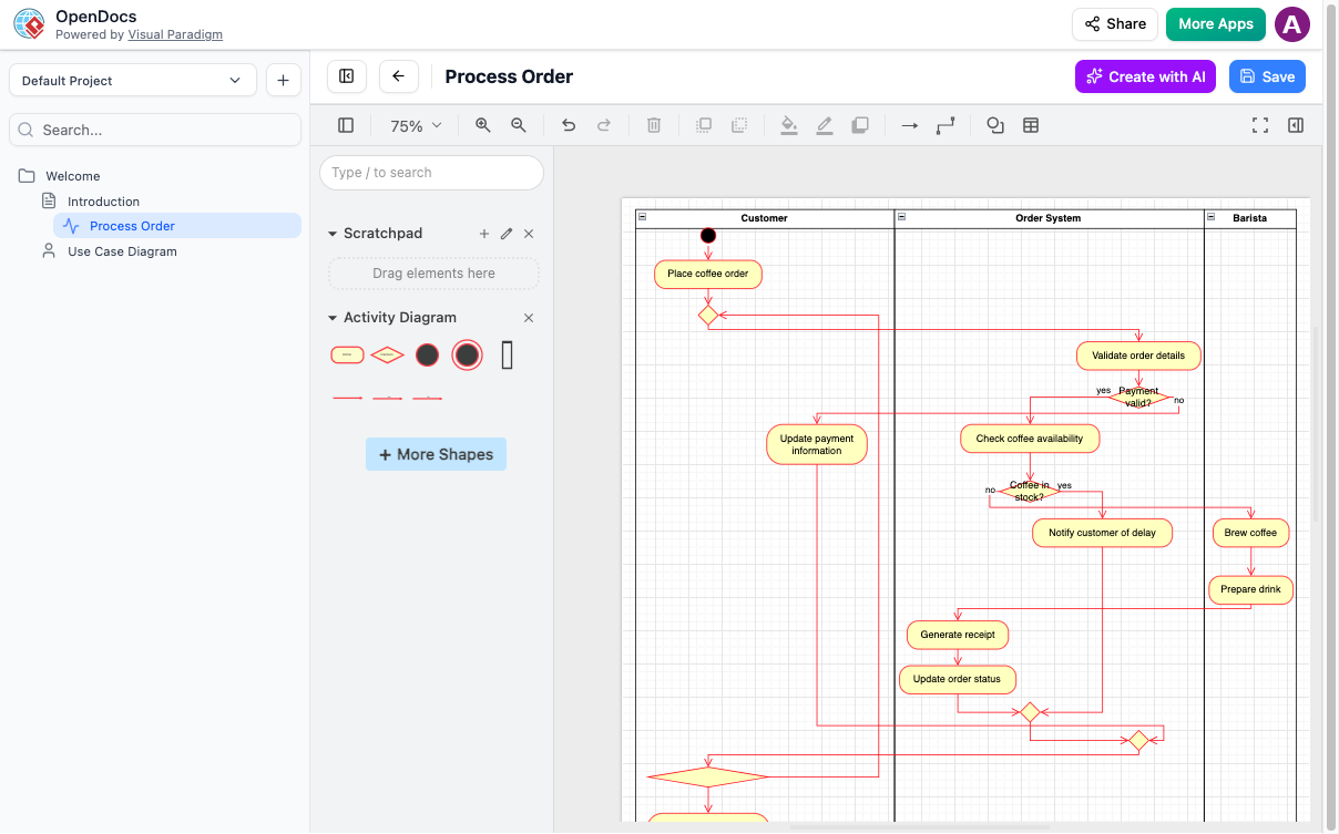
When modeling complex business processes, the challenge often lies not just in defining the steps, but in visualizing how different roles interact and coordinate. This is where the Activity Diagram shines, specifically when utilizing swimlanes. Based on the visual evidence from the Visual Paradigm OpenDocs interface, we are looking at a workflow designed to process a coffee order. This tutorial will walk you through the architecture of this diagram, explaining how to structure parallel processes, manage decision logic, and ensure smooth synchronization between the Customer, Order System, and Barista.
The Power of Swimlanes in System Modeling
The most prominent feature of the diagram shown is the division of the canvas into vertical sections known as swimlanes. In the context of the provided screenshot, we see three distinct lanes:
- Customer: The external actor initiating the process.
- Order System: The internal logic engine handling validation and data management.
- Barista: The execution team responsible for physical preparation.
Using swimlanes is crucial for segregation of duties. It allows stakeholders to immediately see which actor is responsible for a specific action. In a professional architecture review, this prevents ambiguity. For example, if the process stalls at “Check coffee availability,” the diagram clearly indicates this is a system decision, not a human error.
Deconstructing the Workflow Logic
Let’s trace the flow of control from the top of the diagram to the bottom. We will break down the logic into three distinct phases.
1. The Entry Point and Data Validation
Every Activity Diagram begins with a Start Node (the solid black circle). In our case, the flow begins with the Customer placing a coffee order. This is a critical trigger event. The flow immediately crosses into the Order System lane, moving to the Validate order details activity.
Here, we encounter the first Decision Node (represented by a diamond shape). The system evaluates the condition: “Payment valid?”. This is a classic binary decision:
- Yes: The process continues to check inventory.
- No: The process diverts to the Update payment information activity.
2. Inventory Checks and Exception Handling
Once payment is confirmed, the system moves to Check coffee availability. This introduces a second layer of complexity: the inventory check. The decision diamond asks “Coffee in stock?”.
The logic here is vital for a real-world application. If the answer is yes, the flow proceeds to the Barista lane to Brew coffee. However, if the answer is no, the system triggers an exception handler. It sends a notification to the Notify customer of delay. This step highlights the importance of feedback loops in system design—you cannot simply fail silently; you must communicate status updates to the user.
3. Synchronization and Completion
Notice the bottom section of the diagram where multiple lines converge. In Activity Diagrams, this is known as a Synchronization Node (a thick horizontal bar). This node acts as a barrier that only allows the flow to continue once all incoming parallel paths have completed.
In our scenario, the system must wait for two things to happen before finalizing the transaction:
- The receipt must be generated (Order System).
- The drink must be prepared (Barista).
Only when both “threads” of the process meet at the synchronization bar does the flow proceed to Update order status and eventually terminate.
Visualizing the Structure
To implement this logic in OpenDocs or similar UML tools, you rely on specific notations. Below is a representation of how the logic is structured, emphasizing the separation of concerns.
// Swimlane Definitions
[Customer]
  [Start] -> Place coffee order
             -> (Decision: Payment Valid?)
                [Yes] -> [Order System]
                [No]  -> Update payment information

[Order System]
  [Validate order details]
             -> (Decision: Coffee in stock?)
                [Yes] -> [Barista]
                [No]  -> Notify customer of delay

[Barista]
  [Brew coffee] -> Prepare drink

// Synchronization
  [Order System] -> Generate receipt
  [Barista]       -> (Join) -> Update order status
Advanced Modeling Concepts
The diagram in the screenshot demonstrates a robust approach to handling asynchronous tasks. In many real-world coffee shop systems, the brewing process takes time (e.g., 2 minutes), whereas the receipt generation is instant. A well-designed system must handle this time gap gracefully.
The fork and join mechanism used at the bottom of the diagram is the standard solution for this. It allows the Order System to be ready for the next customer while the Barista is still busy. This concept of concurrency is essential for high-throughput system design.
Conclusion
By utilizing the swimlanes and decision nodes available in OpenDocs, you can transform a simple list of steps into a powerful system architecture diagram. Whether you are designing a retail checkout process or a complex backend API workflow, the principles of clear separation of duties and robust synchronization remain the same. Mastering these visual tools allows you to communicate technical requirements effectively to both developers and business stakeholders.