Understanding the internal architecture of a system is critical for robust software design. A Composite Structure Diagram (CSD) serves as a specialized tool within the Unified Modeling Language (UML) to reveal how complex classifiers are composed. Unlike a standard class diagram that focuses on relationships between objects, a composite structure diagram exposes the internal organs of a class. It details the parts, ports, and connectors that make up a whole. This guide walks you through the mechanics of creating these diagrams, ensuring your system architecture is clear, modular, and maintainable.
Whether you are designing a microservices framework, a legacy system refactoring, or a complex embedded controller, visualizing the internal composition helps stakeholders grasp the system’s behavior without getting lost in code. We will explore the syntax, semantics, and practical application of composite structure diagrams. By the end of this reading, you will understand how to map out internal structures effectively.
🧐 What is a Composite Structure Diagram?
A Composite Structure Diagram is a type of structural diagram in UML. It illustrates the internal structure of a classifier, such as a class or component. It shows how the classifier is built from smaller parts and how these parts interact with each other. Think of it as a blueprint for the inside of a box.
- Classifier: The main object being defined (e.g., a Vehicle, a Database Connection Pool).
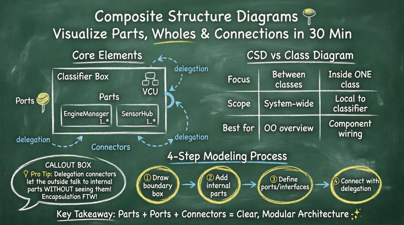
- Parts: The internal components that make up the classifier.
- Ports: The interaction points where parts connect to the outside world or other parts.
- Connectors: The links that establish communication paths between ports.
While standard class diagrams show association, aggregation, and inheritance, they do not show the internal wiring. A CSD fills this gap. It is particularly useful for:
- Designing systems with strict separation of concerns.
- Visualizing how different modules collaborate within a single entity.
- Defining interfaces and required services clearly.
- Managing complexity in large-scale architectures.
🧱 Core Elements of the Diagram
To build a valid composite structure diagram, you must understand the specific notation and rules. Each element has a distinct meaning and function.
1. The Classifier Box
The diagram begins with a rectangle representing the classifier. The top part of the box contains the name of the class. The bottom part contains the internal structure. A special icon in the top right corner indicates it is a composite structure. This box acts as the boundary for the internal components.
2. Parts (Internal Instances)
Parts are instances of other classes located inside the main classifier. They represent the sub-components. For example, a Car classifier might have parts named Engine, Wheel, and SteeringSystem.
- Parts are drawn as smaller rectangles inside the main box.
- Each part has a name and a type (the class it instantiates).
- You can specify multiplicity (e.g., 1..* for multiple wheels).
- Parts are private by default, meaning they are not directly accessible from outside the composite.
3. Ports (Interaction Points)
Ports are the interfaces through which a classifier or a part interacts with the environment. They define how a part exposes its functionality. Without ports, parts are isolated islands inside the classifier.
- Provided Interface: A lollipop shape (circle on a line) indicating functionality offered to the outside.
- Required Interface: A socket shape (half-circle on a line) indicating functionality needed from the outside.
- Ports are placed on the boundary of the part or the classifier.
- They enforce encapsulation by hiding internal implementation details.
4. Connectors (Links)
Connectors define the communication paths between ports. They specify how data or control signals flow. There are two main types of connectors in this context:
- Delegation Connectors: Connect an external port of the classifier to an internal port of a part. This allows the outside world to access internal functionality through the main classifier.
- Internal Connectors: Connect two ports within the classifier. This shows how internal parts talk to each other.
📊 Comparison: CSD vs. Class Diagram
It is common to confuse Composite Structure Diagrams with standard Class Diagrams. Understanding the distinction ensures you use the right tool for the job.
| Feature | Class Diagram | Composite Structure Diagram |
|---|---|---|
| Focus | Relationships between classes | Internal structure of a single class |
| Scope | System-wide or subsystem | Local to one classifier |
| Detail Level | Attributes and Methods | Parts, Ports, and Connections |
| Encapsulation | Visibility modifiers (public/private) | Physical and Logical boundaries |
| Best Used For | Object-oriented design overview | Component architecture and wiring |
🛠️ Step-by-Step Modeling Process
Creating a composite structure diagram requires a methodical approach. Follow these steps to ensure accuracy and clarity.
Step 1: Define the Boundary
Start by drawing the main classifier box. Name it according to the system component you are modeling. Decide if this is a software class, a hardware device, or a business entity. The boundary defines what is internal and what is external.
Step 2: Identify Internal Parts
List the components that make up this classifier. Ask: “What sub-entities are contained within this whole?” For a PaymentGateway, parts might include EncryptionModule, TransactionLogger, and NetworkAdapter.
- Draw rectangles for each part inside the main box.
- Label them clearly with their class names.
- Indicate multiplicity if a part can exist in multiple instances.
Step 3: Define Interfaces (Ports)
For each part, determine what services it needs and what it provides. Place ports on the parts.
- Use the provided interface notation for services the part offers.
- Use the required interface notation for services the part needs.
- For the main classifier, define the public interface. This is how the outside world interacts with the composite.
Step 4: Connect the Parts
Draw lines between the ports to establish communication. This is where the logic of the system comes to life.
- Connect the EncryptionModule to the NetworkAdapter if data must pass between them.
- Use delegation connectors to link the main classifier’s port to a specific internal part’s port. This hides the internal part’s complexity.
- Ensure every required interface has a corresponding provided interface connected to it.
🔗 Understanding Delegation Connectors
Delegation connectors are a unique feature of composite structure diagrams. They represent the delegation of responsibility from the composite to a specific part. This is crucial for maintaining encapsulation.
Imagine a Smartphone classifier. It has a part called ScreenController. The user interacts with the Smartphone’s external touch port. Behind the scenes, this request is delegated to the ScreenController‘s internal touch port. The user does not need to know the controller exists; they only see the phone’s interface.
- Direction: The arrow points from the composite’s required port to the part’s provided port.
- Function: It allows the composite to expose functionality without exposing the part.
- Benefit: It simplifies the external view of the system.
📝 Practical Example: Vehicle Control Unit
Let us apply these concepts to a real-world scenario. Consider a Vehicle Control Unit (VCU) in an automotive system. The VCU manages the engine, brakes, and sensors.
1. The Classifier
The main box is labeled VCU. It acts as the central brain.
2. The Parts
Inside the VCU, we identify:
- EngineManager: Handles fuel injection and ignition.
- BrakeSystem: Manages ABS and hydraulic pressure.
- SensorHub: Collects data from speed, temperature, and pressure sensors.
3. The Ports
The VCU exposes a DiagnosticPort to the outside world. Internally, the SensorHub has a required port for RawData and a provided port for ProcessedData. The EngineManager requires ProcessedData.
4. The Connections
- Internal: Connect SensorHub provided ProcessedData to EngineManager required ProcessedData.
- Delegation: Connect the external DiagnosticPort to the SensorHub‘s diagnostic access point.
This visualization clarifies that the VCU is not a monolithic block but a collection of coordinated parts. It helps developers see where data flows and where bottlenecks might occur.
🎯 Best Practices for Clear Diagrams
Creating a diagram is one thing; making it readable is another. Follow these guidelines to ensure your composite structure diagrams serve their purpose effectively.
- Limit Complexity: Do not draw every single variable. Focus on structural components and significant interactions.
- Use Naming Conventions: Ensure part names reflect their class names clearly. Use prefixes if necessary to denote ownership.
- Group Related Parts: If a classifier has many parts, consider using compartments or nested composite structures to group them logically.
- Document Interfaces: Clearly label the interfaces on ports. Avoid generic names like “Port1”; use descriptive names like “InputStream”.
- Validate Connectivity: Check that all required ports have a matching provided port. Orphaned ports indicate design errors.
- Focus on Behavior: While this is a structural diagram, ensure the connections imply logical data flow.
⚠️ Common Pitfalls to Avoid
Even experienced modelers can make mistakes. Being aware of common errors saves time during the review process.
- Over-Engineering: Modeling every internal method as a separate part creates clutter. Stick to logical components.
- Confusing Parts with Attributes: An attribute is a variable (e.g., an integer ID). A part is a full object with behavior. Do not draw simple variables as parts.
- Missing Delegation: If an external action needs an internal part to execute, you must use a delegation connector. Otherwise, the interaction is undefined.
- Ignoring Multiplicity: Failing to specify if a part is single or multiple can lead to memory management issues in implementation.
- Circular Dependencies: Ensure internal connectors do not create unresolvable loops between parts unless explicitly required.
🔄 Extending to Component Diagrams
Composite Structure Diagrams often sit alongside Component Diagrams in a modeling suite. While a Component Diagram shows the relationship between different software components (like libraries or modules), a Composite Structure Diagram shows the inside of one component.
Use Component Diagrams when:
- You need to show the deployment of modules.
- You are defining boundaries between different projects or teams.
- You are managing dependencies between distinct artifacts.
Use Composite Structure Diagrams when:
- You need to explain the internal wiring of a specific component.
- You are defining the internal API of a class.
- You are refactoring a complex class into smaller sub-components.
📈 Benefits of Internal Visualization
Why invest time in this level of detail? The benefits extend beyond just drawing boxes.
- Improved Communication: Stakeholders can see how the system works without reading code.
- Reduced Coupling: By defining strict ports, you enforce loose coupling between internal parts.
- Testability: Internal parts can be mocked based on their port definitions during unit testing.
- Scalability: Understanding the internal structure helps in planning for future expansion or replacement of parts.
- Documentation: These diagrams serve as living documentation that evolves with the code.
🛑 Advanced Considerations
For complex systems, standard elements may not be enough. Consider these advanced concepts.
Constraints and Guards
You can add constraints to connectors. These are conditions that must be met for the connection to be valid. For example, a PowerConnection might have a guard condition [voltage > 10]. This adds a layer of logical validation to the structural model.
Node and Device
While primarily for software, these diagrams can represent hardware. A Node represents a physical computational resource. You can map software parts to physical nodes to visualize deployment architecture.
Refinement
A composite structure can be refined. A part in one diagram can be the classifier in another. This allows for hierarchical modeling. You start with a high-level composite, then drill down into the details of specific parts in subsequent diagrams.
🧩 Summary of Key Takeaways
Composite Structure Diagrams provide a powerful lens for examining the internal composition of systems. They move beyond simple relationships to show how parts assemble and interact.
- Parts are the internal building blocks.
- Ports define the interaction points.
- Connectors establish the communication pathways.
- Delegation links external interfaces to internal logic.
- Encapsulation is maintained by hiding parts behind the classifier boundary.
By mastering this notation, you enhance your ability to design systems that are modular, testable, and clear. The effort invested in modeling the internal structure pays dividends in reduced bugs and clearer team communication. Use this guide as a reference when you need to dive deep into the architecture of your software.
❓ Frequently Asked Questions
Q: Can I use this for database schemas?
A: Yes, but with limitations. You can model the internal structure of a data access object or a transaction manager. However, for pure data relationships, a relational schema diagram is often more appropriate.
Q: Is this diagram tool-specific?
A: No. It is part of the standard UML specification. Any UML-compliant tool can render it, regardless of the programming language or platform.
Q: How do I handle dynamic parts?
A: Composite structure diagrams are primarily static. For dynamic behavior, you would typically pair this with a Sequence Diagram or State Machine Diagram to show how parts interact over time.
Q: What if I have too many parts?
A: Break the classifier down. If a class has too many internal parts, it may be violating the Single Responsibility Principle. Consider splitting the class into multiple classifiers and modeling the relationships between them.
Q: Do I need to draw every method?
A: No. Focus on the structural components. Methods are internal details of the parts. The diagram is about the composition, not the implementation logic of every function.