


When designing complex software systems, standard class diagrams often fall short. They excel at showing relationships between individual objects, but they struggle to depict how distinct parts of a system interact at a structural level. This is where the Composite Structure Diagram becomes essential. It provides a clear view of the internal architecture of classifiers, specifically focusing on the parts that make up a component and how those parts connect to one another. In this guide, we will walk through the process of modeling a multi-tier application from the ground up using this specific UML notation.
Why Use a Composite Structure Diagram? 🧩
Traditional modeling often stops at the class level. However, real-world applications are built from subsystems, modules, and hardware components. A Composite Structure Diagram allows you to:
- Decompose Complexity: Break down a large class into manageable internal parts.
- Visualize Interaction: Show how data flows between internal components.
- Define Interfaces: Specify the exact contract (ports) through which parts communicate.
- Map Architecture: Align the diagram with physical deployment constraints.
For a multi-tier application, this diagram is invaluable. It distinguishes the presentation layer from the business logic layer and the data persistence layer, ensuring that dependencies are managed correctly.
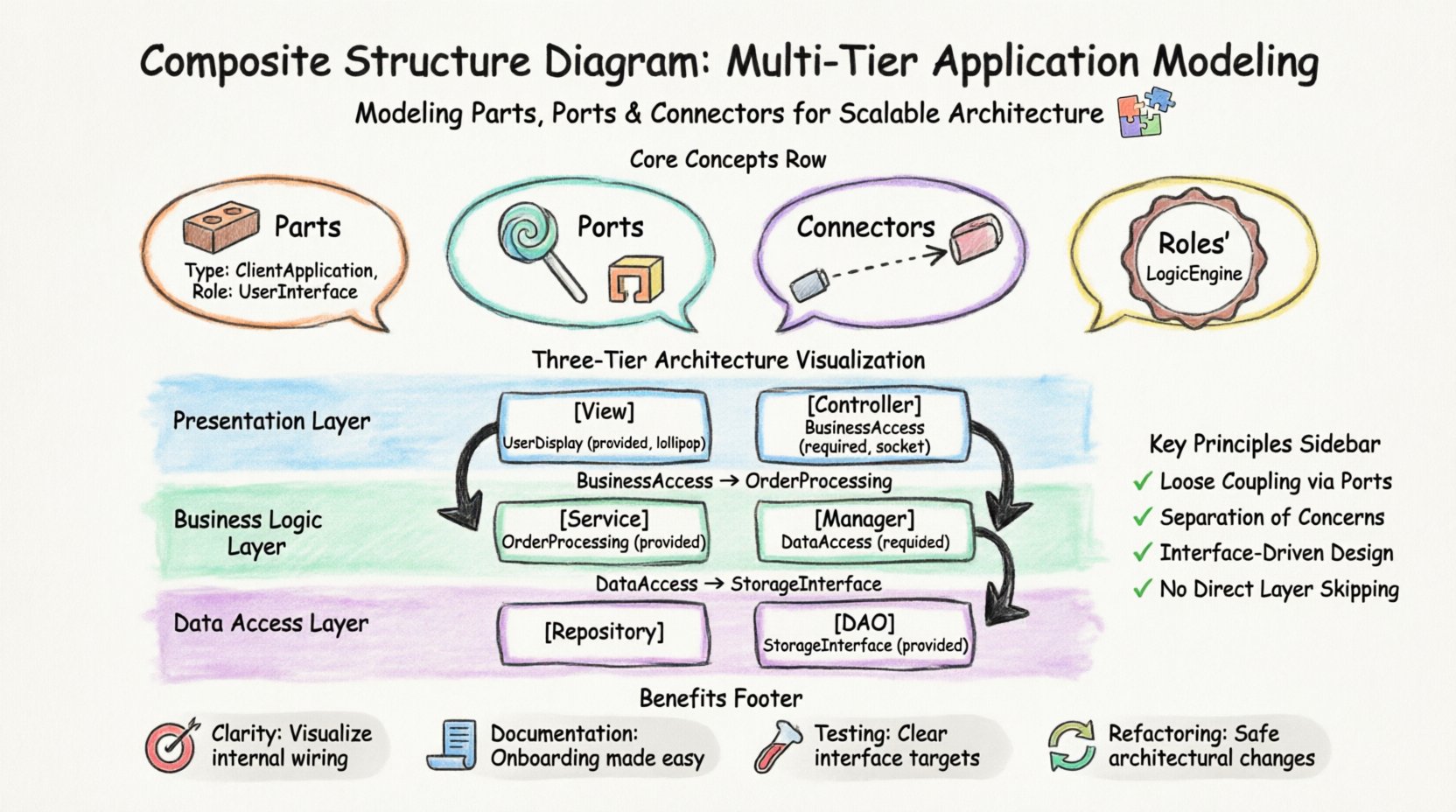
Core Concepts and Terminology 📐
Before diving into the modeling steps, it is crucial to understand the building blocks. Unlike a standard class diagram, the composite structure diagram relies on specific concepts:
1. Parts 🧱
A part represents an instance of a classifier that resides within another classifier. In a multi-tier context, a part could be a Controller, a Repository, or a View. Each part has a defined type and an optional role.
2. Ports 🚪
Ports are interaction points. They define where a part exposes functionality or receives data. Ports are categorized into:
- Provided Interfaces (Lollipop): The functionality the part offers to the outside world.
- Required Interfaces (Socket): The functionality the part needs from the outside world.
3. Connectors 🔗
Connectors link ports together. They represent the flow of information. A connector binds a required interface of one part to a provided interface of another.
4. Roles 🎭
A role defines the specific position a part plays within a connector. It clarifies how a part interacts in a specific context.
Understanding Multi-Tier Architecture 🏢
A multi-tier architecture separates concerns into distinct layers. This separation improves maintainability, scalability, and security. The standard model typically includes three layers:
- Presentation Layer: Handles user interaction and display.
- Business Logic Layer: Contains the core rules and processing.
- Data Access Layer: Manages storage and retrieval of information.
Below is a breakdown of the responsibilities for each tier within a composite structure model.
| Tier | Primary Responsibility | Key Parts | Typical Interface |
|---|---|---|---|
| Presentation | Rendering UI, capturing input | View, Controller | DisplayData, SubmitAction |
| Business Logic | Processing rules, validation | Service, Manager | ProcessOrder, ValidateUser |
| Data Access | Persisting state, querying | Repository, DAO | SaveRecord, FetchData |
Step-by-Step Modeling Walkthrough 📝
Now, we will construct the diagram. We will assume a scenario involving an order management system. We will not reference any specific software tools; the focus remains on the structural modeling technique.
Step 1: Define the Composite Structure 🏗️
Start by defining the main classifier. In this case, let us call it OrderSystem. This classifier acts as the container for the entire multi-tier architecture.
- Create a new class element named OrderSystem.
- Enable the composite structure view (often represented by a rectangle divided into sections).
- This view signifies that the internal composition is now visible.
Step 2: Add the Parts (Tiers) 🧱
Next, decompose the system into its logical tiers. These will be the internal parts of the OrderSystem.
- Part 1: PresentationPart
- Type: ClientApplication
- Role: UserInterface
- Part 2: BusinessPart
- Type: CoreServices
- Role: LogicEngine
- Part 3: DataPart
- Type: StorageManager
- Role: PersistenceLayer
Draw these parts inside the boundary of the OrderSystem classifier. Each part should be clearly labeled with its type and role.
Step 3: Define Ports and Interfaces 🚪
This is the most critical step for ensuring loose coupling. Each part needs to know exactly what it requires and what it provides.
PresentationPart Ports
- Required: Needs to call business logic. Create a port named BusinessAccess.
- Provided: Needs to display results to the user. Create a port named UserDisplay.
BusinessPart Ports
- Required: Needs to save data. Create a port named DataAccess.
- Provided: Needs to accept requests from the presentation. Create a port named OrderProcessing.
DataPart Ports
- Provided: Needs to allow writing and reading. Create a port named StorageInterface.
- Required: None (usually the bottom of the chain).
Step 4: Connect the Parts 🔗
Now, establish the connections between the ports. This visualizes the data flow.
- Connection 1: Connect BusinessAccess (Required) on PresentationPart to OrderProcessing (Provided) on BusinessPart.
- Connection 2: Connect DataAccess (Required) on BusinessPart to StorageInterface (Provided) on DataPart.
These connectors represent the API calls or method invocations that occur at runtime. They ensure that the Presentation Layer cannot talk directly to the Data Layer. This enforces the architectural boundary.
Advanced Modeling Patterns 🔍
As the system grows, simple connections may not be enough. Consider these advanced patterns for complex scenarios.
1. Nested Composite Structures
If the BusinessPart is large enough, it can have its own internal structure. You can model the BusinessPart as a composite itself, containing sub-parts like ValidationService and TransactionManager. This recursive approach allows for deep nesting without cluttering the main diagram.
2. External Interfaces
Not all connections are internal. Your multi-tier application might communicate with an external payment gateway. You can represent this using a Boundary or an external classifier connected via a connector to the BusinessPart.
3. State-Based Interaction
Sometimes, a part only provides an interface in certain states. While standard UML does not always capture dynamic state changes in a static diagram, you can annotate the ports with preconditions. For example, the StorageInterface might require the system to be in an Active state.
Common Pitfalls and How to Avoid Them ⚠️
When creating these diagrams, teams often make specific mistakes that reduce the diagram’s value. Review this list to ensure accuracy.
- Skipping Ports: Connecting parts directly without ports creates tight coupling. Always define a port for every connection.
- Over-Modeling: Do not model every single variable. Focus on the structural boundaries and major data flows.
- Ignoring Types: Ensure the type of the part matches the implementation. If the part is a Repository, the type should reflect that.
- Circular Dependencies: Check that data does not flow in a circle (e.g., Data → Business → Presentation → Data). This indicates a design flaw.
Validation and Refinement 🔨
Once the diagram is drawn, validation is necessary. Review the structure against the following criteria:
- Separation of Concerns: Does the Presentation Layer handle only UI logic? Does the Data Layer handle only storage?
- Interface Consistency: Do the provided and required interfaces match in name and signature?
- Completeness: Is there a path for every major user action from the UI to the Database?
- Scalability: Can you easily swap the DataPart for a different storage mechanism without changing the PresentationPart?
Mapping to Deployment ⚙️
A composite structure diagram often precedes a deployment diagram. The parts defined here usually map to physical nodes in the infrastructure.
- PresentationPart → Web Server / Client Device
- BusinessPart → Application Server
- DataPart → Database Server
By maintaining this mapping, you ensure that the logical model aligns with the physical reality. If a part is too heavy, you might need to split it across multiple physical nodes, which the composite structure diagram can help plan.
Benefits of This Approach ✅
Using this structured approach offers several advantages over ad-hoc modeling:
- Clarity: Stakeholders can see the internal wiring of the system without getting lost in code.
- Documentation: The diagram serves as living documentation for onboarding new developers.
- Testing: The defined interfaces provide clear targets for unit and integration testing.
- Refactoring: When changing the backend, the diagram helps identify which parts of the frontend are affected.
Final Considerations 🚀
Modeling a multi-tier application requires discipline. It is not enough to simply draw boxes and lines; you must understand the contracts between those boxes. The Composite Structure Diagram is the tool that enforces this discipline. By focusing on parts, ports, and connectors, you create a blueprint that is resilient to change.
Remember that diagrams are communication tools. If a diagram cannot be understood by a new team member, it fails its purpose. Keep the notation consistent. Use clear names for ports. Ensure the hierarchy is logical. With practice, this technique becomes a natural part of your architectural design process.
As you refine your skills, you will find that these diagrams help you spot architectural drift early. When a developer tries to bypass the business layer, the diagram makes that violation obvious. This proactive approach to design saves significant time during the development and maintenance phases.
Start small. Model a single module first. Then expand to the full system. This incremental approach prevents overwhelm and ensures that every connection is intentional and documented.