

Mastering Inheritance in UML: Best Practices and Implementation Guidelines
In the realm of system architecture and object-oriented design, the Unified Modeling Language (UML) Class Diagram serves as the blueprint for software structure. Among the various relationships available, inheritance (generalization) stands out as a fundamental mechanism for promoting code reuse, establishing clear taxonomies, and reducing redundancy. However, visualizing this relationship correctly is often more complex than simply drawing a line between classes.
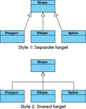
When modeling complex domains, such as a geometric shapes library, developers often encounter variations in diagrammatic representation. As illustrated in the industry-standard example of shape inheritance, the semantic meaning remains identical even if the visual connectors differ. This guide explores the best practices for modeling inheritance hierarchies, ensuring your diagrams remain clear, maintainable, and aligned with modern software engineering standards.
Understanding the Semantics of Generalization
The core principle of inheritance is the “Is-A” relationship. A Circle is a Shape, just as a Square is a Shape. In UML, this is represented by a generalization relationship, typically depicted by a solid line with a hollow triangle arrowhead pointing toward the superclass (the parent).
While the visual syntax is standardized, real-world modeling often reveals subtle variations in how these connectors are drawn. In the context of the Shapes hierarchy, you may observe two distinct styles of connectors:
- The Standard Arrow: A direct line connecting the subclass to the superclass with the triangle at the superclass end.
- The Indirect or Grouped Line: A connector that may route through a central point or utilize a specific layout style to accommodate complex diagrams.
Key Insight: Despite visual differences in the connector path or style, these representations are semantically equivalent. The UML specification defines the relationship by the arrowhead and the target class, not by the specific pixel-perfect trajectory of the line.
Best Practices for Inheritance Hierarchy Design
To ensure your UML diagrams effectively communicate system architecture, adhere to the following guidelines when modeling inheritance:
1. Prioritize Semantic Clarity Over Aesthetic Consistency
The primary goal of a class diagram is communication. If drawing a connector in a specific way helps avoid overlapping lines or clarifies the scope of a complex hierarchy, do so. However, ensure that the arrowhead remains unambiguous. Never sacrifice the directionality of the inheritance arrow for the sake of a “cleaner” look.
2. Avoid Deep Inheritance Hierarchies
While inheritance is powerful, deep trees (e.g., Shape → GeometricFigure → PlanarFigure → 2DShape → Circle) often indicate design flaws. A flat or moderately deep hierarchy is usually more maintainable.
- Guideline: Limit inheritance depth to three or four levels. If you find yourself needing more, consider using composition or aggregation instead.
- Why: Deep hierarchies make refactoring difficult and increase the risk of the “Fragile Base Class” problem.
3. Use Abstract Classes for Common Prototypes
In the Shapes example, Shape is typically an abstract class. It defines the contract (e.g., calculateArea()) but cannot be instantiated directly. In UML, mark abstract classes by italicizing the class name or adding the {abstract} stereotype.
Common Pitfalls and Anti-Patterns
Even experienced architects fall into traps when modeling inheritance. Be vigilant against these common anti-patterns:
Anti-Pattern: The “God Class” Hierarchy
Creating a single superclass that holds all logic for every subclass leads to bloated parent classes. If Shape contains specific logic for drawing a Triangle, that is a violation of the Single Responsibility Principle.
Anti-Pattern: Mixing Implementation Details with Structure
Do not clutter the inheritance diagram with implementation details such as specific method signatures or variable types unless they are critical to the interface contract. Focus on the class structure and relationships.
Anti-Pattern: Circular Dependencies
Inheritance must be acyclic. A subclass cannot inherit from a class that eventually inherits from it. While UML tools often prevent this, logical errors in the design can lead to infinite loops in code generation.
Optimal Implementation Patterns
When transitioning from your UML diagram to actual code (e.g., in Java, C#, or C++), ensure the implementation matches the visual model:
- Interface vs. Abstract Class: If the relationship is purely behavioral (e.g.,
Drawable), consider using Interfaces. If there is shared state or default behavior, use Abstract Classes. - Polymorphism: Ensure your code leverages the inheritance hierarchy through polymorphic calls. A method accepting a
Shapeparameter should work seamlessly with any subclass. - Visibility Modifiers: Respect the visibility modifiers defined in your diagram. Private methods in a superclass should not be exposed to subclasses unless necessary, and protected members should be used judiciously.
Conclusion
Modeling inheritance in UML is a balance between strict adherence to standards and practical flexibility. As seen in the Shapes hierarchy example, the specific visual style of the connector is secondary to the semantic correctness of the relationship. By focusing on shallow hierarchies, abstract base classes, and clear “Is-A” relationships, you create diagrams that not only look professional but also guide the development of robust, maintainable software systems.
Remember: A diagram is a contract between the design and the implementation. Keep it clear, keep it semantic, and avoid the traps of over-engineering.