


Understanding how components interact within a software system is crucial for architects and developers. UML Sequence Diagrams provide a clear visual representation of these interactions over time. They focus on the dynamic behavior of a system, showing how objects communicate to achieve a specific goal. This guide explores the fundamental concepts, patterns, and best practices for creating effective sequence diagrams without relying on specific tools or software products.
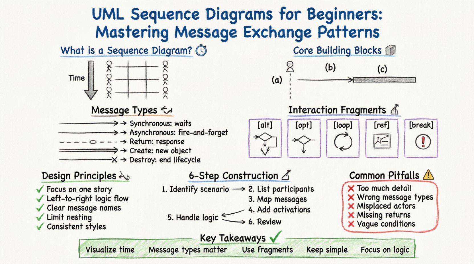
What is a Sequence Diagram? ⏳
A sequence diagram is a type of interaction diagram. It describes the interactions between objects or parts in terms of a sequence of messages. Unlike other diagrams that show static structure, this diagram focuses on the time dimension. It answers the question: “In what order do events happen?”
Focus: Interaction flow and timing.
Participants: Objects, actors, and systems.
Orientation: Vertical axis represents time flowing downwards.
Horizontal Axis: Represents different participants across the system.
Core Building Blocks 🧱
Before constructing a diagram, you must understand the elements that make it up. These elements form the vocabulary of the diagram.
1. Lifelines
A lifeline represents a participant in the interaction. It is drawn as a dashed vertical line extending from the participant’s box. It signifies the existence of the object over time.
Actor: A human user or external system. Represented by a stick figure.
Object: An instance of a class. Represented by a rectangle with a colon (e.g.,
Order: OrderController).System Boundary: A box enclosing all objects belonging to a specific system context.
2. Messages
Messages are arrows connecting lifelines. They represent communication between participants. The style of the arrow indicates the type of message.
3. Activation Bars
An activation bar (or execution occurrence) is a thin rectangle placed on a lifeline. It shows the period during which the object is performing an action or waiting for a response.
Types of Message Exchange Patterns 🔄
Understanding the specific types of messages is essential for accurate modeling. Each pattern conveys different timing and control flow semantics.
Message Type | Arrow Style | Behavior | Use Case |
|---|---|---|---|
Synchronous Call | Solid line, filled arrowhead | Caller waits for callee to finish. | Function calls requiring immediate data. |
Asynchronous Call | Solid line, open arrowhead | Caller does not wait; continues immediately. | Background tasks, fire-and-forget. |
Return Message | Dashed line, open arrowhead | Response from callee to caller. | Returning data or status. |
Create Message | Double line, filled arrowhead | Instantiates a new object. | Creating a new record or instance. |
Destroy Message | Line ending in an ‘X’ | Ends the object’s lifecycle. | Removing a temporary object. |
Interaction Fragments 🧩
Complex systems rarely follow a single linear path. Interaction fragments allow you to model conditional logic, loops, and optional behaviors within the sequence.
1. Alt (Alternative)
Used when the flow depends on a condition. It looks like a rectangle with a dashed line labeled alt at the top. Inside, you define different scenarios based on boolean expressions.
Structure: Multiple operands separated by dashed lines.
Labeling: Each operand has a condition (e.g.,
[user is logged in]).Example: If a payment fails, show an error. If it succeeds, show a receipt.
2. Opt (Optional)
Similar to alt, but represents a single optional block. If the condition is false, the block is skipped entirely.
Condition: One condition at the top (e.g.,
[show confirmation]).Usage: For features that are not always present, like saving a draft.
3. Loop
Represents repeated interactions. It is framed by a rectangle labeled loop.
Iteration: Can specify conditions like
[while user exists].Optimization: If the loop runs a single time, it can be simplified.
Example: Processing a list of items in a shopping cart.
4. Ref (Reference)
Used to break down complex diagrams into smaller, manageable pieces. It references another sequence diagram.
Delegation: “Call to another diagram”.
Context: Keeps the main diagram clean from excessive detail.
5. Break
Indicates a block that only executes under exceptional conditions, such as an error or exception handling.
Label:
break.Condition: Usually an error state (e.g.,
[connection failed]).
Timing and Activation ⏱️
Activation bars are critical for understanding concurrency and blocking behavior.
Duration: The length of the bar indicates the duration of the activity.
Overlapping: If two activation bars overlap on different lifelines, it implies parallel processing.
Self-Message: A message sent from an object to itself. Often shown with a loop arrow on the same lifeline.
Design Principles for Clarity 🛠️
A diagram is useless if it cannot be read. Adhering to design principles ensures the diagram serves its purpose.
1. Keep it Focused
Do not try to model the entire system in one diagram. Split diagrams by use case or functionality. A single diagram should ideally tell one specific story.
2. Logical Ordering
Arrange participants logically. Place the initiator on the left and the system or database on the right. This mirrors the natural reading direction.
3. Consistent Naming
Use clear, descriptive names for messages. Avoid generic terms like “Do it”. Instead, use “Validate Order” or “Fetch User Profile”.
4. Limit Depth
Deep nesting of interaction fragments makes diagrams hard to follow. Use ref to offload complexity to separate diagrams.
5. Color and Style
Even without CSS, visual distinction helps. Use standard line styles consistently. Do not mix solid and dashed lines arbitrarily.
Common Pitfalls to Avoid ⚠️
Even experienced practitioners make mistakes. Be aware of these common errors.
Too Much Detail: Including every single database query clutters the diagram. Focus on the business logic flow.
Wrong Message Types: Using synchronous calls for background tasks creates a false impression of blocking behavior.
Misplaced Actors: Placing an actor inside a system boundary when they are external.
Ignoring Return Messages: Forgetting to show the return path can make the flow look incomplete.
Unclear Conditions: Writing vague conditions in
altblocks leads to ambiguity.
Step-by-Step Construction Guide 📝
Follow this workflow to create a robust sequence diagram.
Step 1: Identify the Scenario
Define the starting point (e.g., User clicks “Submit”).
Define the end point (e.g., Confirmation message shown).
Step 2: List Participants
Identify all objects involved in the scenario.
Determine if any are actors or external systems.
Draw their lifelines.
Step 3: Map the Messages
Draw arrows from sender to receiver.
Label the messages clearly.
Ensure the arrows flow from top to bottom.
Step 4: Add Activation Bars
Place bars where the object is busy processing.
Ensure bars align with the message duration.
Step 5: Handle Logic
Insert
alt,opt, orloopframes where needed.Define conditions for each branch.
Step 6: Review and Refine
Check for consistency in arrow styles.
Verify that all paths lead to a logical conclusion.
Ensure no dead ends exist.
Advanced Considerations 🔍
As you gain experience, consider these nuances.
1. Concurrency
Real systems often handle multiple requests. Use overlapping activation bars to show parallel execution. This is vital for performance analysis.
2. Asynchronous Callbacks
Some systems rely on callbacks. Represent these with dashed return arrows that are not necessarily immediate. This distinguishes them from standard return messages.
3. State Changes
While sequence diagrams focus on interaction, they imply state changes. Ensure that the sequence reflects valid state transitions.
4. Documentation
Sequence diagrams are living documents. Update them when the system logic changes. They serve as a contract between design and implementation.
Summary of Key Takeaways ✅
Visualize Time: Sequence diagrams show the flow of events over time.
Message Types Matter: Distinguish between synchronous and asynchronous calls.
Use Fragments:
alt,loop, andopthandle complexity.Keep it Simple: Avoid clutter by splitting diagrams by use case.
Focus on Logic: Prioritize business logic over technical implementation details.
By mastering the elements of message exchange, you create a blueprint that guides development and testing. These diagrams bridge the gap between abstract requirements and concrete code. They facilitate communication among stakeholders, ensuring everyone understands the system’s behavior before a single line of code is written.
Remember, the goal is clarity. A diagram that confuses is worse than no diagram at all. Always prioritize readability and accuracy. With practice, you will develop an intuition for which interactions deserve detailed modeling and which can be summarized.