


Understanding how components interact over time is critical in system design. A Unified Modeling Language (UML) Sequence Diagram provides a clear visual representation of these interactions. This guide walks you through the mechanics, syntax, and logic required to create effective sequence diagrams. Whether you are designing a microservice architecture or mapping user workflows, mastering this notation ensures clarity across development teams.
🤔 What is a Sequence Diagram?
A sequence diagram is a type of interaction diagram. It details how operations are carried out by showing the messages exchanged between objects over time. Unlike a class diagram, which focuses on structure, the sequence diagram focuses on behavior and the flow of control.
- Time flows vertically: Interactions happen from top to bottom.
- Participants are horizontal: Objects, systems, or users sit across the top.
- Messages define logic: Arrows indicate the transfer of data or requests.
This visual tool helps developers identify bottlenecks, verify logic paths, and document complex asynchronous processes before writing code.
🧱 Core Building Blocks
Before drawing, you must understand the notation. Every sequence diagram relies on a few fundamental elements.
1. Participants (Lifelines)
A participant represents an entity involved in the interaction. This could be a user, a database, a server, or an internal class.
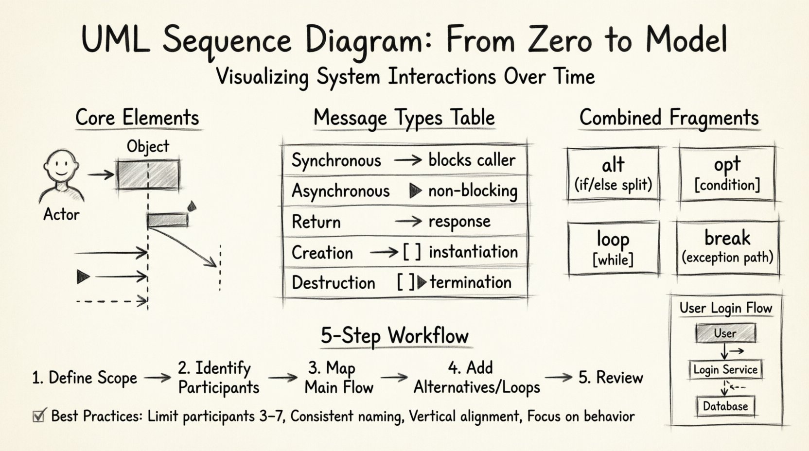
- Actor: Represented by a stick figure. Usually an external human or system.
- Object: Represented by a rectangle with a dashed underline (e.g.,
SystemName::ObjectName). - Boundary: Represents the interface between the system and the outside world.
- Lifeline: The vertical dashed line extending down from the participant. It represents the lifespan of that object.
2. Messages
Messages travel between lifelines. They drive the logic forward.
- Synchronous Call: Solid line with a solid arrowhead. The sender waits for a response before continuing.
- Asynchronous Call: Solid line with a filled arrowhead. The sender does not wait.
- Return Message: Dashed line with an open arrowhead. Indicates a response or data return.
- Self-Message: An arrow that loops back to the same lifeline. Used for internal processing.
3. Activation Bars
A narrow rectangle placed on a lifeline. It indicates when an object is performing an action or is actively processing a message. If an activation bar is present, the object is busy.
📊 Types of Messages Explained
Distinguishing between message types is vital for accurate modeling. The table below clarifies when to use which notation.
| Message Type | Visual Symbol | Behavior | Use Case |
|---|---|---|---|
| Synchronous | ──> | Blocks caller | Requesting data, waiting for a result. |
| Asynchronous | ──► | Non-blocking | Fire-and-forget tasks, logging, notifications. |
| Return | —► | Response | Returning a value or status code. |
| Creation | ──>[ ] | Instantiation | Creating a new object instance. |
| Destruction | [ ]► | Termination | Deleting or ending an object’s life. |
🔄 Combined Fragments
Real-world logic is rarely linear. Combined fragments allow you to model conditional logic, loops, and optional steps. They are enclosed in a rectangle labeled with a keyword.
1. Alt (Alternative)
Used for if/else logic. The diagram splits into different frames based on conditions.
- Label: alt
- Structure: Multiple frames separated by dashed lines.
- Example: If user is logged in, show dashboard; else, show login screen.
2. Opt (Optional)
Represents a block that may or may not occur. It is similar to Alt but implies a single optional path.
- Label: opt
- Condition: [condition is true]
- Usage: Validation checks that might fail.
3. Loop
Indicates a repeated action. It can be a fixed count or a condition.
- Label: loop
- Condition: [while condition is true]
- Usage: Iterating through a list of items.
4. Break
Similar to Alt, but used to represent an exception or a path that breaks the normal flow.
- Label: break
- Usage: Error handling or aborting a transaction.
🛠️ Step-by-Step: Creating Your First Diagram
Follow this structured approach to build a sequence diagram from scratch. This method ensures logical consistency and readability.
Step 1: Define the Scope
Identify the specific scenario you are modeling. A sequence diagram should not attempt to show the entire system at once. Focus on a single user story or transaction.
- Start Point: Which actor initiates the action?
- End Point: What is the final outcome or state?
- Context: Are we looking at the external interface or internal logic?
Step 2: Identify Participants
List every entity involved in this specific scenario. Do not include everything in the system, only what is necessary for this flow.
- Who is the user?
- Which service handles the request?
- Is a database involved?
- Are there external APIs?
Step 3: Map the Main Flow
Draw the happy path first. This is the sequence of events that occurs when everything works correctly.
- Start with the first message from the actor.
- Add the subsequent internal calls.
- End with the final response.
Step 4: Add Alternatives and Loops
Once the main path is clear, layer in the complexity. Use alt frames for conditional logic and loop frames for iterations.
- Where might the process fail?
- Are there repeated checks required?
- Do we need to handle errors differently?
Step 5: Review and Refine
Check for clarity. Ensure activation bars align with message starts and ends. Remove redundant messages that do not add value.
🎯 Best Practices for Readability
A diagram that is too complex defeats its purpose. Adhere to these guidelines to maintain clarity.
- Limit Width: Keep the number of participants to a manageable number (3-7 is ideal). If you have more, consider breaking the diagram into smaller scenarios.
- Consistent Naming: Use clear names for objects. Avoid generic terms like “Object1”.
- Vertical Alignment: Align return messages with their corresponding calls when possible.
- Use Fragments Wisely: Don’t nest
altframes too deeply. It becomes hard to read. Use separate diagrams for deeply nested logic. - Focus on Behavior: Do not clutter the diagram with data attributes unless they are critical to the interaction.
🚫 Common Mistakes to Avoid
Even experienced modelers make errors. Watch out for these common pitfalls.
1. Ignoring Timing
Sequence diagrams imply time. If a message is sent before a participant is created, the model is invalid. Ensure the creation message happens before any interaction with that object.
2. Overloading Messages
Do not pack multiple actions into a single message label. For example, “Get User, Validate, Save” should be broken down. Each step should ideally be a distinct interaction.
3. Mixing Levels of Abstraction
Do not mix high-level system boundaries with low-level database queries in the same diagram. Keep the level of detail consistent.
4. Missing Return Messages
While not always mandatory, omitting return messages can make the flow feel incomplete. It is good practice to show where data returns, especially in synchronous calls.
📝 Advanced Scenarios
As you gain proficiency, you will encounter more complex patterns.
Recursion
Sometimes an object calls itself. This is shown with a loop arrow on the same lifeline. This often represents a recursive function call in code.
Message Ordering
Messages must flow top to bottom. If a message originates from a later point in time, it must be drawn lower on the page. Do not cross lines arbitrarily unless it represents a return.
Parallelism
In some notations, you can show parallel processing. If two objects act independently at the same time, you can group their interactions without strict vertical dependency. However, standard sequence diagrams usually enforce a strict top-down order.
🧩 Example Walkthrough: User Login
Let’s apply these concepts to a concrete example. We will model a standard user login process.
- Actor: User
- System: Login Service
- Data: Database
Flow:
- User enters credentials and clicks “Submit”.
- Frontend sends request to Login Service.
- Login Service queries Database for user hash.
- Database returns hash.
- Service compares hash with input.
- Service returns “Success” or “Failure”.
This linear flow can be expanded with alt frames to handle cases like “Account Locked” or “Invalid Email Format”. Using loop frames is not necessary here unless we are retrying failed attempts.
📈 Benefits of Documentation
Creating these models offers tangible benefits beyond the drawing itself.
- Communication: Serves as a common language between developers and stakeholders.
- Gap Analysis: Helps identify missing logic before implementation begins.
- Testing: Provides a basis for integration test cases.
- Maintenance: Serves as documentation for future developers understanding the flow.
🔗 Conclusion on Workflow
Building sequence diagrams is a skill that improves with practice. Start with simple flows and gradually add complexity. Remember that the goal is clarity, not perfection. A diagram that helps your team understand the system is a successful diagram. Focus on the interactions, respect the timing, and keep your notation consistent.
By following the steps outlined in this guide, you can move from understanding the basics to creating robust models that drive better software design. Keep your focus on the logic flow, and let the notation support your intent.