


Software architecture is evolving at a pace that challenges traditional documentation methods. As systems grow in complexity, distributed across cloud environments, microservices, and event-driven architectures, the need for clear communication remains paramount. UML sequence diagrams have long served as the backbone for visualizing interactions between system components. However, the static nature of legacy modeling approaches is colliding with the dynamic requirements of modern development.
This guide explores the trajectory of sequence diagrams, moving from static documentation to active, living artifacts that support continuous integration, automated testing, and real-time collaboration. We will examine how these diagrams integrate with code, leverage automation, and adapt to the complexities of contemporary system design.
Understanding the Current Landscape 📊
Before projecting forward, it is necessary to understand where the practice stands today. A sequence diagram primarily focuses on the order of interactions between objects or services over time. It captures the flow of messages, the state of lifelines, and the logic governing control flow.
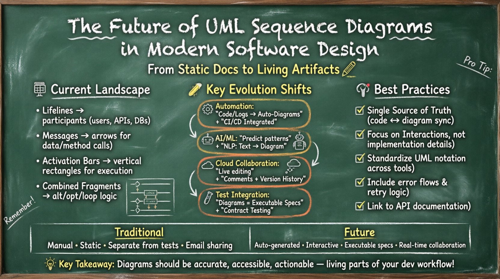
- Lifelines: Represent participants in the interaction, such as users, databases, or external APIs.
- Messages: Arrows indicating data transfer or method calls between lifelines.
- Activation Bars: Vertical rectangles showing when an object is active or executing a procedure.
- Combined Fragments: Constructs like alt (alternative), opt (optional), and loop that define conditional or repeated logic.
While these elements remain standard, the context in which they are applied has shifted significantly. Modern applications do not run as monolithic blocks. They are composed of numerous services that must coordinate without tight coupling. This necessitates a diagrammatic approach that can handle high levels of abstraction while maintaining technical precision.
Challenges in Modern Architectures 🧩
The shift towards microservices and cloud-native development introduces specific challenges for traditional modeling. A single user request might traverse dozens of services before a response is generated. Mapping this flow manually on a diagram is prone to error and quickly becomes outdated.
1. Complexity of Distributed Systems
In a distributed environment, latency, failure modes, and network partitions are constants. Standard sequence diagrams often omit these non-functional aspects to keep the visual clear. However, ignoring them in the design phase leads to fragile systems.
- Latency Visualization: How do we represent time delays in a way that impacts performance planning?
- Failure Handling: Where do retries, fallbacks, and circuit breakers fit into the message flow?
- Asynchronous Messaging: Traditional diagrams favor synchronous calls. Event-driven systems rely on publish-subscribe patterns that require different notation.
2. The Documentation Gap
There is often a disconnect between the codebase and the diagrams. Developers frequently update code but neglect to update the visual models. This creates a “documentation debt” where the diagrams no longer reflect reality. In agile and DevOps environments, this lag is unacceptable.
The Shift Towards Automation ⚙️
The most significant trend in the future of sequence diagrams is the move from manual drawing to automated generation. If a diagram is to remain accurate, it must be generated from the source of truth: the code itself.
Automated documentation tools analyze code execution paths, API contracts, or logs to reconstruct interaction flows. This approach ensures that the diagram always mirrors the implementation.
- Code-to-Diagram: Static analysis tools parse method calls and class structures to propose sequence flows.
- Log-to-Diagram: Runtime tracing data can be processed to show actual message sequences that occurred in production.
- API Definition Integration: OpenAPI specifications and GraphQL schemas provide structured data that can be rendered into interaction models without manual intervention.
This automation reduces the maintenance burden. Instead of a developer spending hours updating a drawing, the system updates the diagram when the code changes. This aligns documentation with the continuous integration pipeline.
Integration with AI and Machine Learning 🤖
Artificial intelligence is beginning to influence how we design and interpret system interactions. It is not just about generating diagrams; it is about predicting interactions and identifying potential bottlenecks before they occur.
Predictive Modeling
Machine learning models trained on existing codebases can suggest interaction patterns. If a new service is added to an architecture, the AI can propose a sequence diagram that aligns with established patterns in the codebase. This helps maintain consistency across a large team.
- Pattern Recognition: Identifying common sequences like authentication, data retrieval, and error handling.
- Recommendation Engines: Suggesting the most efficient message ordering based on historical performance data.
- Anomaly Detection: Highlighting sequence flows that deviate from the norm, potentially indicating bugs or security risks.
Natural Language Processing
Writing diagrams often requires knowledge of specific syntax. Natural Language Processing (NLP) allows developers to describe interactions in plain text, which the system converts into a formal sequence diagram. This lowers the barrier to entry for stakeholders who may not be familiar with UML notation.
For example, a developer might write, “User logs in, then requests data. If data is missing, show error.” The system translates this into lifelines, messages, and conditional fragments automatically.
Real-Time Collaboration and Cloud-Based Modeling ☁️
Software design is no longer a solitary activity. Teams are distributed across time zones, requiring tools that support simultaneous editing and version control. The future of sequence diagrams lies in cloud-native platforms that function similarly to collaborative document editors.
Features of Collaborative Platforms
- Live Cursor Tracking: See where other team members are editing in real time.
- Comment Threads: Discuss specific messages or lifelines directly on the diagram.
- Version History: Roll back changes or compare different design iterations easily.
- Access Control: Manage who can view or edit specific parts of the architecture.
This shift transforms the diagram from a static file into a shared workspace. It encourages dialogue about system design rather than just passing files back and forth.
Bridging the Gap Between Design and Test 🧪
One of the most promising applications of future sequence diagrams is their direct integration into automated testing frameworks. Instead of diagrams being purely for documentation, they become executable specifications.
Contract Testing
When a sequence diagram defines the expected interaction between a client and a server, it can serve as a contract. Automated tests verify that the actual code adheres to this contract. If the sequence deviates, the test fails.
- Specification as Code: Diagram definitions are stored alongside code in version control.
- Test Generation: Test cases are derived from the message flows defined in the diagram.
- Regression Prevention: Ensures that refactoring does not break expected interaction patterns.
Abstraction Levels and Contextual Views 👁️
As systems grow, a single diagram cannot capture everything. The future involves managing multiple views of the same system, each at a different level of abstraction.
Stratification of Detail
Stakeholders require different levels of detail. A product manager might need a high-level view of user flows, while a backend engineer needs the specific API payload exchanges. Modern modeling tools support nested diagrams or linked views.
- Business Level: Focuses on user goals and high-level transactions.
- System Level: Focuses on service interactions and data flow.
- Component Level: Focuses on specific class methods and internal logic.
Navigation between these layers allows users to drill down from a business requirement to a specific code implementation without losing context.
Comparison: Traditional vs. Future-Focused Approaches 📋
To clarify the differences, we can compare how traditional modeling differs from the emerging standards.
| Feature | Traditional Approach | Future-Focused Approach |
|---|---|---|
| Creation | Manual drawing with mouse and keyboard | Automated generation from code or logs |
| Accuracy | Prone to drift from implementation | Synchronized with the codebase |
| Format | Static image or offline file | Interactive, web-based, and linked |
| Testing | Separate from design | Executable specifications for testing |
| Collaboration | File sharing and email | Real-time multi-user editing |
| Integration | Isolated from CI/CD pipelines | Integrated into deployment workflows |
Best Practices for Modern Modeling 🛠️
To adapt to these changes, teams should adopt specific practices that align with the future of sequence diagrams.
1. Maintain Single Source of Truth
Ensure that the diagram and the code are not competing sources. If the code changes, the diagram must update automatically. If the diagram is manually updated, it must be treated as a specification that requires code changes to match.
2. Focus on Interactions, Not Implementation
While technical precision is vital, diagrams should not become implementation details. Avoid showing every variable assignment. Focus on the exchange of messages and the flow of control.
3. Standardize Notation
Even as tools evolve, the underlying notation (UML) should remain consistent. This ensures that diagrams can be understood by any tool or team member, regardless of the platform used.
4. Include Error Flows
Happy paths are easy to diagram. The value lies in documenting exception handling, timeouts, and retry logic. Modern diagrams should explicitly show these failure modes.
5. Integrate with API Documentation
Link sequence diagrams directly to API reference documents. This provides context for developers reading the API spec, showing how endpoints fit into the larger system flow.
The Human Element 🤝
Technology changes, but the need for human communication remains. Diagrams are a tool for discussion, not just a record of the past.
- Workshops: Use diagrams as the center of design workshops to align team understanding.
- Onboarding: Use existing diagrams to help new developers understand the system quickly.
- Code Reviews: Review interaction flows in diagrams alongside code changes to catch architectural drift.
The goal is to facilitate understanding. If a diagram confuses the reader, it has failed, regardless of its technical accuracy. Clarity should always take precedence over complexity.
Looking Ahead: Standards and Interoperability 🌐
As the ecosystem grows, interoperability between different tools becomes crucial. We are seeing a move towards open standards for modeling data. This allows teams to switch tools without losing their intellectual property.
- Model Interchange Formats: Using open formats like XMI or JSON-based representations of models.
- API-First Design: Defining the interface before the implementation, with diagrams serving as the contract.
- Cloud Portability: Ensuring diagrams can be exported and imported across different cloud environments.
This standardization prevents vendor lock-in and ensures that documentation remains accessible even if the primary tooling changes.
Summary of Key Shifts 🔑
The evolution of UML sequence diagrams is driven by the need for speed, accuracy, and collaboration. The static drawings of the past are being replaced by dynamic, interactive models.
- Automation reduces maintenance overhead.
- AI enhances predictive capabilities and ease of use.
- Cloud enables real-time teamwork.
- Testing integration ensures reliability.
Teams that embrace these shifts will find themselves better equipped to manage complex systems. The diagrams become a living part of the development lifecycle, not an afterthought.
Final Thoughts on Architectural Clarity 🌟
Designing software is fundamentally about managing complexity. Sequence diagrams offer a way to visualize that complexity without losing sight of the details. As tools evolve, they must remain focused on this core purpose.
The future belongs to diagrams that are accurate, accessible, and actionable. By integrating them into the daily workflow of development and testing, teams can ensure that their architecture remains clear and robust. This approach supports long-term maintainability and reduces the risk of technical debt.
As you plan your next project, consider how sequence diagrams can evolve alongside your code. Prioritize automation, collaboration, and clarity. These principles will guide you through the complexities of modern software design.