
The architecture of complex software systems relies heavily on visual modeling to communicate design intent. Among the Unified Modeling Language (UML) suite, the Composite Structure Diagram stands out as a specialized tool for revealing the internal anatomy of classifiers. Unlike standard class diagrams that focus on static relationships, this diagram type dives deeper into the composition, interactions, and boundaries of internal parts. This review examines current modeling practices, identifying strengths and weaknesses in how these diagrams are constructed and utilized within modern development lifecycles.
🧩 Understanding the Core Concept
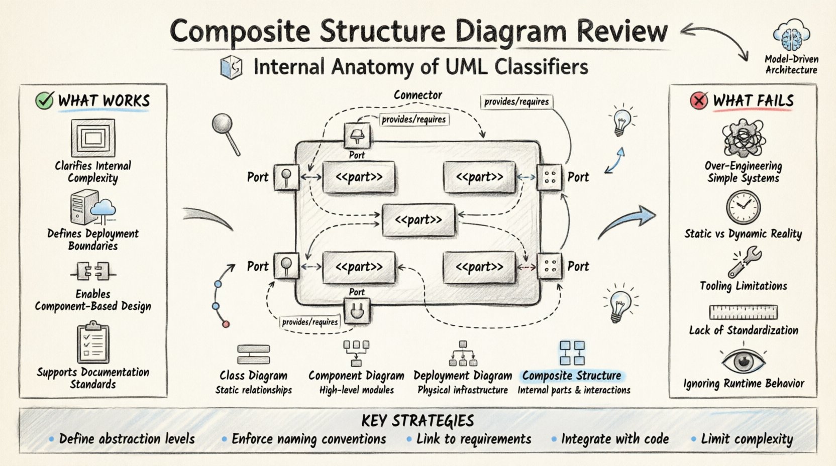
A Composite Structure Diagram provides a view of the internal structure of a classifier. It shows how the classifier is composed of smaller parts, how these parts interact through ports, and how they collaborate to fulfill specific responsibilities. This level of detail is crucial when moving from abstract design to concrete implementation.
When modeling complex subsystems, simply knowing that a class exists is insufficient. Teams need to understand how that class is built from the inside out. This diagram bridges the gap between logical design and physical deployment. It allows architects to visualize:
Internal Parts: The constituent elements that make up the whole.
Interfaces: The contracts that define how parts communicate.
Connectors: The links that route data between ports.
Collaborations: The behavior patterns enabled by the structure.
While often overlooked in favor of Sequence or Class diagrams, the internal structure view is vital for ensuring modularity and maintainability. It forces the architect to define boundaries clearly, preventing tight coupling between components.
🛠️ Key Components Explained
To effectively utilize this modeling technique, one must understand the specific notation and elements involved. Each component serves a distinct purpose in defining the internal topology.
1. Parts
Parts represent the instances of classifiers contained within the composite. They are the building blocks. A part is often depicted as a small rectangle with the stereotype <<part>> or simply by its name and type. Understanding the lifecycle of a part is essential; some are created dynamically, while others exist for the duration of the composite.
2. Ports
Ports are interaction points. They define where a part can connect to the outside world or to other parts within the same composite. A port has a specific type, which dictates the interfaces it can provide or require. This separation of interface from implementation is a key principle of good design.
3. Connectors
Connectors link ports together. They represent the flow of information or control. In a diagram, these are lines that join the interaction points of different parts. Proper use of connectors ensures that data flows logically without ambiguity.
4. Interfaces
Interfaces specify a set of operations without defining their implementation. In this context, they define the contract between the composite and its environment, or between internal parts. Using interfaces decouples the parts from their specific implementations, allowing for greater flexibility.
✅ What Works in Current Practices
Despite the complexity, many engineering teams find significant value in using composite structure diagrams. When applied correctly, they enhance clarity and reduce technical debt.
1. Clarifying Internal Complexity
For large, monolithic systems, understanding the internal composition is difficult. A single class diagram can become cluttered with hundreds of attributes and methods. By breaking a class down into a composite structure, architects can hide internal complexity. This abstraction allows stakeholders to focus on high-level interactions without getting lost in implementation details.
2. Defining Deployment Boundaries
These diagrams are excellent for mapping logical components to physical nodes. When combined with deployment diagrams, they provide a clear picture of where software runs. This is particularly useful in distributed systems where parts of a composite might reside on different servers or containers.
3. Facilitating Component-Based Design
Component-based development relies heavily on well-defined interfaces. This diagram type enforces that discipline. By explicitly defining ports and interfaces, teams ensure that parts can be swapped out without affecting the rest of the system. This supports the principle of loose coupling.
4. Supporting Documentation Standards
In regulated industries, documentation is not optional. These diagrams provide a standardized way to document internal logic. Auditors and reviewers can trace how a specific function is achieved by following the connectors and ports. This traceability is a significant advantage for compliance.
❌ What Fails and Why
While powerful, the use of composite structure diagrams is not without pitfalls. Many teams struggle with adoption, leading to diagrams that are either ignored or created incorrectly.
1. Over-Engineering Simple Systems
Not every class needs a composite structure diagram. Applying this level of detail to simple data models or utility classes adds unnecessary overhead. Teams often create these diagrams for trivial components, wasting time that could be spent on coding or testing.
2. Static Nature vs. Dynamic Reality
UML diagrams are inherently static. They capture a snapshot in time. However, modern systems are highly dynamic. Parts may be created, destroyed, or moved at runtime. A composite structure diagram often fails to capture this fluidity, leading to a disconnect between the model and the running system.
3. Tooling Limitations
Modeling tools vary significantly in their support for composite structures. Some tools struggle to maintain consistency when diagrams are updated. If a port is renamed in one diagram, it might not update in another. This fragmentation leads to confusion and errors.
4. Lack of Standardization
There is no universal standard for how these diagrams should be drawn. Different teams use different conventions for naming parts or labeling connectors. This inconsistency makes it difficult for new team members to understand existing designs.
5. Ignoring Runtime Behavior
Focus often shifts too much to structure and not enough to behavior. A composite structure diagram shows how parts are connected, but not necessarily how they behave. Without accompanying state or activity diagrams, the diagram can feel incomplete.
📊 Comparative Analysis
To understand where this diagram fits in the broader modeling ecosystem, it helps to compare it with other common UML types.
Diagram Type | Primary Focus | Best Used For | Limitation |
|---|---|---|---|
Class Diagram | Static relationships and attributes | Database schema and general logic | Lacks internal structure detail |
Component Diagram | High-level modules and dependencies | System architecture overview | Does not show internal composition |
Deployment Diagram | Hardware and software infrastructure | Physical distribution of artifacts | Misses logical internal structure |
Composite Structure | Internal parts and interactions | Deep dive into class internals | Static view, high maintenance |
🚀 Implementation Strategies
To maximize the value of these diagrams, teams should adopt specific strategies that mitigate common failures.
1. Define Abstraction Levels
Do not attempt to model every class at the composite level. Identify the core subsystems that require deep inspection. For high-level views, use component diagrams. For low-level implementation, use composite structure diagrams. This tiered approach keeps documentation manageable.
2. Enforce Naming Conventions
Consistency is key. Establish a naming convention for parts, ports, and interfaces. For example, always prefix parts with their type or role. This reduces cognitive load when reading the diagram.
3. Link to Requirements
Every part and connector should trace back to a requirement or a design decision. This ensures that the diagram is not just a drawing exercise but a functional part of the engineering process. It also helps in impact analysis when requirements change.
4. Integrate with Code
Where possible, use tools that generate code from models or reverse engineer code into models. This synchronization ensures that the diagram remains accurate as the code evolves. Manual updates are prone to drift and eventual obsolescence.
5. Limit Complexity
Keep the number of parts and connectors manageable. If a diagram becomes too crowded, it loses its value. Break large composites into smaller, nested structures. Use grouping boxes to organize related parts.
🔄 Maintenance and Evolution
A model is only useful if it remains accurate. In agile environments, where code changes frequently, maintaining static diagrams is challenging.
1. Version Control Integration
Treat diagrams as code. Store them in version control systems. This allows teams to track changes over time and revert if necessary. It also facilitates code reviews for architectural decisions.
2. Regular Audits
Schedule periodic reviews of the diagrams. Check if they match the current implementation. If parts have been refactored, update the diagram. If a diagram is outdated, mark it as such or archive it.
3. Training and Onboarding
Ensure all team members understand how to read and create these diagrams. Training reduces the risk of inconsistent modeling. New hires should be able to understand the internal structure without needing extensive verbal explanations.
🔮 Future Trends
The landscape of software modeling is evolving. As systems become more distributed and cloud-native, the role of structural diagrams is shifting.
1. Model-Driven Architecture
Model-Driven Architecture (MDA) aims to automate code generation from models. This increases the reliance on accurate structural diagrams. If the model is wrong, the generated code will be wrong.
2. Cloud-Native Design
In microservices architectures, the boundaries between services are critical. Composite structure diagrams can help define the internal structure of a service, ensuring it does not become a monolith again.
3. AI-Assisted Modeling
Artificial Intelligence tools are beginning to assist in diagram generation. These tools can suggest structures based on code analysis. This could reduce the manual effort required to maintain these diagrams.
💡 Final Thoughts on Modeling
The Composite Structure Diagram is a powerful tool for understanding the internal mechanics of software systems. It provides a level of detail that standard class diagrams cannot match. However, it requires discipline and care to use effectively. Teams must balance the need for detail with the cost of maintenance.
Success lies in knowing when to use it. It is not a replacement for other diagrams but a complement. When used alongside sequence and deployment diagrams, it paints a complete picture of the system. By avoiding common pitfalls and adhering to best practices, engineering teams can leverage this model to build more robust, maintainable, and scalable software architectures.
The goal is not to create perfect diagrams, but to create useful ones. If a diagram helps a developer understand a system faster, it has succeeded. If it becomes a burden that slows down development, it needs to be re-evaluated. Continuous improvement in modeling practices is the only way to keep pace with the complexity of modern software.