


In the landscape of software architecture and systems engineering, visualizing internal structures is critical. A Composite Structure Diagram (CSD) offers a unique window into the internal composition of a classifier. While often overshadowed by Class or Sequence diagrams, its ability to depict parts, ports, and connectors provides indispensable clarity for complex systems. This guide explores efficient techniques and workflow optimizations designed to streamline the creation of these diagrams. By adopting structured shortcuts and logical patterns, modelers can accelerate the prototyping phase without sacrificing accuracy.
Whether you are designing microservices, embedded systems, or modular applications, the speed at which you can iterate on structural models impacts project velocity. This article focuses on practical methods to enhance your workflow. We will examine the anatomy of the diagram, discuss strategies for rapid creation, and outline best practices for maintaining clarity as complexity grows.
🧩 Understanding the Anatomy of a Composite Structure Diagram
Before optimizing the creation process, one must understand the fundamental building blocks. A Composite Structure Diagram describes the internal structure of a classifier. It details how parts are arranged and how they interact. Unlike a standard Class Diagram, which focuses on static attributes and operations, a CSD focuses on physical or logical composition.
Key Elements Defined
To work efficiently, you must recognize the distinct roles of the following elements:
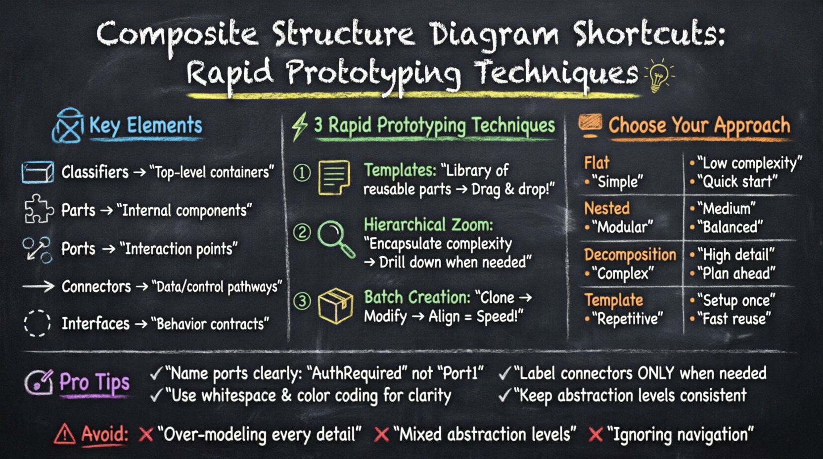
- Classifiers: The top-level containers, often representing the main system or subsystem being modeled.
- Parts: Instances of classifiers contained within the composite structure. They represent the internal components.
- Ports: Interaction points where parts connect with the outside world or other internal parts.
- Connectors: Links that define the pathways for information or control between ports.
- Interfaces: Abstract definitions of behavior that ports must implement or require.
Understanding these definitions prevents common errors during the prototyping phase. Confusing a Part with a Class, or a Port with an Attribute, leads to models that do not accurately reflect system behavior. Rapid prototyping relies on speed, but speed without accuracy results in technical debt.
⚡ Techniques for Rapid Prototyping and Workflow Optimization
Efficiency in diagramming is less about memorizing keyboard combinations and more about establishing a repeatable workflow. When you remove friction from the creation process, you can focus on the logic of the architecture. The following strategies help reduce the cognitive load during diagram construction.
1. Leverage Standardized Templates
Every project has recurring structural patterns. Instead of drawing a new composite structure from scratch for every module, define standard templates. These templates should include common parts and interfaces that are frequently reused.
- Establish a Library: Create a collection of pre-defined parts and interfaces for common patterns like Data Storage, User Interface, or Network Gateway.
- Reuse Logic: When a new component requires a standard configuration, drag it from your library rather than building it element by element.
- Version Control: Keep these templates updated. As your architecture evolves, your templates should reflect the new standard.
2. Hierarchical Zooming
One of the most effective techniques for managing large diagrams is the use of nested structures. Instead of cluttering one view with every detail, use hierarchy to encapsulate complexity.
- Encapsulation: Treat complex sub-structures as single parts within a higher-level diagram.
- Drill-Down: Only open the nested structure when you need to define the internal logic of that specific part.
- Focus: This keeps the main view clean and allows stakeholders to understand the high-level flow without getting lost in implementation details.
3. Batch Creation of Similar Elements
When multiple parts share the same properties, create them in batches. This reduces the number of clicks and interactions required.
- Clone and Modify: Create one part, duplicate it, and adjust the specific properties of the copy.
- Grouping: Select multiple elements to move or align them simultaneously.
- Consistency Checks: Use batch operations to ensure naming conventions and color coding remain consistent across the diagram.
📊 Comparison of Modeling Approaches
Selecting the right approach for your diagram is vital for efficiency. Below is a comparison of different modeling strategies to help you choose the right method for your specific context.
| Approach | Best Used For | Complexity Level | Time Investment |
|---|---|---|---|
| Flat Structure | Simple components with few internal parts | Low | Minimal |
| Nested Hierarchy | Modular systems with distinct sub-systems | Medium | Moderate |
| Decomposition | Complex systems requiring detailed interface mapping | High | Significant |
| Template-Based | Repetitive patterns across multiple modules | Variable | Low (after setup) |
🔗 Managing Internal Connections and Interfaces
Connectors are the lifeblood of a Composite Structure Diagram. They define how data and control signals flow between parts. However, excessive connectors can create a “spaghetti” effect that hinders readability. Efficient management of these connections is essential for rapid prototyping.
Interface Implementation Strategies
Interfaces allow parts to communicate without knowing the specific identity of the other part. This decoupling is crucial for flexible design.
- Provided vs. Required: Clearly distinguish between interfaces a part provides and those it requires. Use distinct visual markers or colors if the tool allows.
- Port Naming: Name ports based on the interface they implement. A port named “AuthRequired” is clearer than “Port1”.
- Grouping: Group related ports together. If a part has five ports for logging, group them visually to reduce visual noise.
Connector Management
Direct connections between parts are straightforward, but managing them in a large diagram can become difficult. Consider the following:
- Auto-Layout: If the environment supports it, use automatic layout algorithms to organize connectors logically.
- Routing Styles: Standardize connector routing (e.g., orthogonal lines vs. curved lines). Consistency helps the eye track the flow.
- Labeling: Label connectors only when necessary. If the relationship is obvious from the port names, omit the label to save space.
🧠 Handling Complexity and Scale
As systems grow, so does the complexity of the diagrams. A diagram that was simple to prototype can become unwieldy within a few iterations. The following techniques help maintain manageability.
Modularization
Do not attempt to draw the entire system in a single view. Break the system down into logical modules.
- Domain Separation: Separate diagrams for Business Logic, Data Access, and Infrastructure.
- Layering: Use layers to separate concerns. Keep the user interface structure separate from the database structure.
- Navigation: Ensure links between diagrams are clear. A part in one diagram should reference a specific diagram where its internal structure is defined.
Visual Clarity
Visual clutter is the enemy of rapid prototyping. If you cannot understand the diagram at a glance, you cannot iterate on it quickly.
- Whitespace: Use whitespace intentionally to separate distinct groups of parts.
- Color Coding: Assign colors to specific types of parts (e.g., Red for critical services, Blue for utility functions).
- Font Hierarchy: Use larger fonts for classifier names and smaller fonts for attributes.
🛠️ Best Practices for Naming and Organization
Consistency in naming is a shortcut in itself. When you know exactly what a part is called, you do not have to search for it or guess its function.
Naming Conventions
Establish a set of rules for naming parts, ports, and connectors. Adhere to these rules strictly.
- Prefixes: Use prefixes to indicate type, such as “P-” for Part or “I-” for Interface.
- CamelCase: Use CamelCase for names to improve readability.
- Context: Include the domain in the name if there is ambiguity. For example, “UserAuthPort” instead of just “AuthPort”.
Documentation within the Diagram
While diagrams should be self-explanatory, sometimes text is necessary. Keep these annotations concise.
- Notes: Use note elements for specific constraints or assumptions.
- Constraints: Add text constraints for data types or performance requirements directly on the element.
- Versioning: Include a version number or date on the diagram itself to track changes over time.
⚠️ Common Pitfalls to Avoid
Even experienced modelers make mistakes that slow down the prototyping process. Being aware of these common pitfalls can save significant time.
1. Over-Modeling
It is tempting to model every possible interaction. However, a diagram should represent the current design, not every potential future state.
- Focus on the Core: Model the primary paths of data and control.
- Defer Details: If a part is not critical to the current prototype, keep it abstract.
- Iterate: Add detail in subsequent iterations rather than trying to get it right the first time.
2. Ignoring Navigation
If a diagram is too large, it becomes unusable. Ensure that navigation between different parts of the model is intuitive.
- Hyperlinks: If the tool allows, link parts to their detailed views.
- Index: Create an index diagram that lists all major components and their locations.
- Search: Ensure you can search for elements quickly within the model.
3. Inconsistent Abstraction Levels
Do not mix high-level views with low-level details in the same view.
- Uniformity: Ensure all parts in a view are at the same level of abstraction.
- Separation: If you need to show both, use separate diagrams.
- Clarity: Mixing levels confuses the reader about what is internal and what is external.
🔄 Workflow Optimization Checklist
To ensure you are maintaining high efficiency throughout your modeling sessions, use this checklist. It serves as a quick reference for your workflow.
- ☐ Are templates defined for common components?
- ☐ Is the hierarchy structured to minimize flat complexity?
- ☐ Are interface names consistent with port names?
- ☐ Is whitespace used effectively to separate groups?
- ☐ Are connectors labeled only when necessary?
- ☐ Is there a clear navigation path between diagrams?
- ☐ Are naming conventions followed strictly?
- ☐ Have annotations been checked for relevance and brevity?
🏁 Final Considerations for Structural Modeling
Creating efficient Composite Structure Diagrams is a balance between technical precision and workflow speed. By focusing on standardization, hierarchy, and clear interface definitions, you can reduce the time spent on the diagramming tool and increase the time spent on architectural decision-making. The shortcuts discussed here are not merely about saving clicks; they are about reducing cognitive load.
When you remove friction from the modeling process, the quality of the architecture improves. You can iterate faster, spot errors earlier, and communicate the system design more effectively to stakeholders. The goal is not to create the most complex diagram, but the most useful one. Rapid prototyping is about getting the structure right quickly so that you can move forward with implementation confidence.
Adopt these techniques consistently. Over time, the efficiency gains will compound, allowing you to handle increasingly complex systems with the same level of ease. The structure of your software is the foundation of its success, and investing time in efficient modeling practices pays dividends throughout the development lifecycle.
Remember that diagrams are living documents. They evolve as the system evolves. Keep your templates updated, your naming conventions consistent, and your focus on clarity. With these practices in place, your structural modeling will remain a reliable asset rather than a burden.