


Software architecture relies heavily on clear definitions of how systems interact. When modeling complex applications, the Composite Structure Diagram (CSD) offers a detailed view of the internal structure of classifiers. However, the boundaries between components often become a source of confusion. Ambiguities in these boundaries can lead to implementation errors, integration failures, and maintenance nightmares. This guide provides a deep dive into resolving these structural uncertainties using standard modeling techniques.
Understanding the Core Concepts 🏗️
A Composite Structure Diagram is a specialized type of diagram in the Unified Modeling Language (UML). It depicts the internal arrangement of a classifier and the interactions between its parts. Unlike a Class Diagram, which focuses on static relationships, or a Sequence Diagram, which focuses on dynamic behavior, the CSD focuses on the physical and logical assembly of the system.
The primary challenge lies in defining the Component Boundary. This boundary acts as a contract. It dictates what is exposed to the outside world and what remains encapsulated within the component. When this boundary is not clearly defined, the following issues arise:
- Dependency Confusion: Parts inside the component rely on external services that are not officially exposed.
- Interface Mismatch: Required interfaces do not match provided interfaces of other parts.
- Logical Leakage: Internal implementation details become visible to external consumers.
- Deployment Errors: The physical deployment does not match the logical structure.
To resolve these issues, one must understand the fundamental elements that make up a component boundary. These elements include parts, ports, interfaces, and connectors.
Anatomy of a Component Boundary 🔍
Before fixing ambiguities, we must define what constitutes a boundary. In UML modeling, a component is a modular, replaceable part of a system. The boundary is the interface through which the component communicates.
1. Parts and Roles
Parts are the internal components that make up the composite structure. Each part must have a defined role. A role defines the expected behavior of the part within the context of the composite. If a part does not have a role, its connection to the rest of the system is ambiguous.
- Strong Typing: Ensure every part is typed with a specific classifier.
- Multiplicity: Define how many instances of a part can exist within the boundary (e.g., one-to-many).
- Ownership: Clarify if the part is owned by the composite or shared with other composites.
2. Ports and Interfaces
Ports are the points of interaction. They are the gateways through which messages enter or leave the component. Interfaces define the set of operations available at that port.
- Provided Interfaces: Operations that the component offers to the outside world.
- Required Interfaces: Operations that the component needs from the outside world.
- Internal Ports: Connections strictly within the boundary.
Ambiguity often occurs when a part interacts with the outside world without going through a port. This bypasses the boundary contract. To resolve this, all external interactions must be routed through explicit ports.
Common Ambiguities and Resolution Strategies 🛠️
Modelers frequently encounter specific scenarios where the boundary definition becomes unclear. The table below outlines common problems and their technical resolutions.
| Ambiguity Type | Description | Resolution Strategy |
|---|---|---|
| Shared State | Multiple parts access the same data store directly. | Encapsulate the data store within a single part and expose it via a provided interface. |
| Direct Connections | Parts connect directly to other composites without ports. | Insert a port on the composite boundary and route the connection through it. |
| Interface Inheritance | A part requires an interface that is not defined at the composite level. | Ensure the composite requires the interface, or delegate the requirement to a specific part. |
| Boundary Crossing | A connector crosses the boundary line without a port. | Redraw the connector to terminate at a port node on the boundary. |
| Implementation Leakage | Internal class dependencies are exposed as public. | Move internal classes to a private package or internal compartment. |
Resolving Interface and Port Conflicts ⚡
One of the most persistent sources of ambiguity is the mismatch between what a component needs and what it provides. This often happens in large-scale systems where multiple teams work on different parts of the architecture.
The Contract Principle
Every port represents a contract. If a port is marked as required, the composite assumes it will find an implementation externally. If it is marked as provided, the composite promises to implement it. Confusion arises when:
- A required interface is too generic, allowing any implementation.
- A provided interface exposes internal logic that should remain hidden.
- Realization relationships are implied rather than explicit.
Step-by-Step Resolution
- Identify the Source of Demand: Determine which internal part requires the service. Is it the whole component, or just a sub-part?
- Define the Interface Signature: Create a clear interface definition. Avoid mixing data structures with behavior.
- Assign the Port: Attach the interface to a specific port on the boundary.
- Verify Realization: Ensure another component provides the realization of this interface.
- Check Multiplicity: Confirm that the number of provided instances matches the number of required instances.
Internal Structure vs. External View 🧱
Clarity is often lost when the internal structure is conflated with the external view. A Composite Structure Diagram should clearly separate what is visible from what is hidden.
Internal Compartments
Use the internal compartment of the classifier to show the arrangement of parts. Do not place external connectors here unless they are internal to the composite. If a connector leaves the boundary, it must attach to a port.
- Internal Connectors: These connect parts within the same boundary. They do not cross the boundary line.
- External Connectors: These cross the boundary line and must attach to ports.
Visibility Constraints
Visibility modifiers (+, -, #) play a crucial role in boundary definition.
- Public (+): Visible to all external clients.
- Private (-): Visible only to internal parts.
- Protected (#): Visible to subclasses and internal parts.
Ambiguity occurs when internal parts are marked as public but should remain private. Review the visibility of every part to ensure encapsulation is maintained.
Validation and Verification Techniques ✅
Once the diagram is drafted, it requires validation. This process ensures that the structural model is consistent with the behavioral model and the deployment model.
Consistency Checks
Run the following checks against your diagram:
- Port Completeness: Are all external connections attached to ports?
- Interface Consistency: Do all required interfaces have a corresponding provided interface?
- Role Assignment: Does every part have a defined role?
- No Cycles: Are there circular dependencies between internal parts that do not pass through a port?
Behavioral Alignment
The structure must support the behavior. If a sequence diagram shows a message being sent to a part, the Composite Structure Diagram must show a path for that message. This path should go through the appropriate port.
- Traceability: Link state machine diagrams to the component parts they interact with.
- Message Flow: Ensure the direction of the arrow on the connector matches the flow of data.
Advanced Scenarios and Edge Cases 🚀
Standard modeling rules cover most cases, but complex architectures often introduce edge cases that require careful handling.
1. Nested Composites
When a component contains another component as a part, the boundary of the inner component becomes an internal boundary. Do not expose the inner component’s ports directly to the outer world unless explicitly routed through the outer component’s ports.
- Encapsulation: The outer component should act as a facade for the inner component.
- Delegation: Use delegation connectors to route requests from the outer port to the inner port.
2. Shared Parts
Sometimes a part is shared between multiple composites. This creates a potential ambiguity regarding ownership and lifecycle.
- Shared Aggregation: Use shared aggregation to indicate that the part exists independently of the composite.
- Lifecycle Management: Clearly define who is responsible for creating and destroying the shared part.
3. Dynamic Structure
Some systems change their structure at runtime. A static Composite Structure Diagram cannot capture every dynamic variation.
- Factory Patterns: Model the creation of parts using a factory pattern within the diagram.
- Configuration: Use configuration files or metadata to define the runtime structure, referencing them in the diagram notes.
Best Practices for Clarity 📝
To maintain a high-quality model over time, adhere to these best practices.
- Keep Diagrams Small: If a component is too complex, split it into sub-composites. A single diagram should focus on one level of abstraction.
- Use Naming Conventions: Name ports based on the interface they use, not the part they connect to. This makes the interface contract clearer.
- Document Assumptions: If a boundary assumption is non-standard, add a note to the diagram explaining the constraint.
- Review Iteratively: Do not try to perfect the boundary on the first draft. Refine it as the system design evolves.
- Standardize Symbols: Ensure that the symbols for provided and required interfaces are consistent across all diagrams.
Troubleshooting Common Errors 🔧
Even experienced modelers make mistakes. Here are specific steps to take when you encounter common errors during the review process.
Error: The Connector Crosses the Boundary
Solution: Insert a port on the boundary line. Move the end of the connector to snap to the port. Ensure the port has the correct interface type.
Error: Parts are Floating
Solution: Parts must be connected to something. If a part has no connections, it is likely a mistake. Either remove it or connect it to a port.
Error: Interface Mismatch
Solution: Compare the operation signatures of the required and provided interfaces. Ensure parameter types match exactly.
Error: Circular Dependencies
Solution: Break the cycle by introducing an intermediate interface or refactoring the logic to remove the direct dependency.
The Role of Automation in Boundary Resolution 🤖
While manual review is essential, modeling tools can assist in detecting boundary violations. Automated analysis can check for:
- Unconnected ports.
- Missing interface realizations.
- Violations of encapsulation rules.
Using validation rules within the modeling environment helps maintain consistency. However, automation cannot replace human judgment regarding the semantic meaning of the boundaries.
Summary of Key Takeaways 📌
Resolving ambiguities in component boundaries requires a disciplined approach to UML modeling. By strictly adhering to the rules of ports, interfaces, and connectors, you can create a robust architectural model.
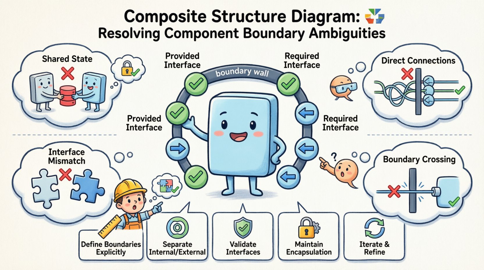
- Define Boundaries Explicitly: Use ports for all external interactions.
- Separate Internal and External: Do not mix internal connectors with external connections.
- Validate Interfaces: Ensure all required interfaces have providers.
- Maintain Encapsulation: Keep internal details hidden behind provided interfaces.
- Iterate and Refine: Treat the diagram as a living document that evolves with the system.
By following these guidelines, you ensure that the Composite Structure Diagram serves its purpose: providing a clear, unambiguous blueprint for system implementation.