


Understanding the architecture of complex software systems requires more than just listing classes or functions. It demands a view into the internal anatomy of components and how they interact at a granular level. The Composite Structure Diagram serves this purpose within the Unified Modeling Language (UML). This guide provides a deep dive into its structure, purpose, and application without relying on specific tools or vendor-specific terminology.
For new developers entering the field of systems design, grasping this diagram type is crucial for visualizing internal collaborations. It bridges the gap between high-level component diagrams and low-level class diagrams. Below, we explore the mechanics, rules, and practical applications of this essential modeling artifact.
🧩 What is a Composite Structure Diagram?
A Composite Structure Diagram is a type of behavioral diagram in UML that illustrates the internal structure of a classifier. It shows the internal parts of a classifier and the relationships between them. Unlike a standard Class Diagram, which focuses on attributes and operations, this diagram focuses on the decomposition of a complex element.
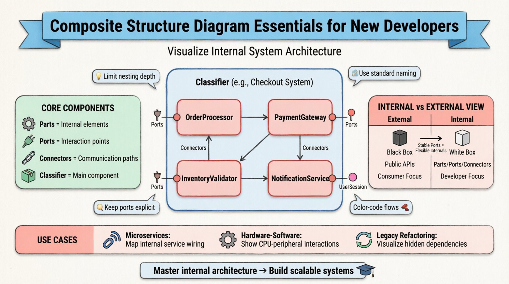
- Classifier: The main element being analyzed (e.g., a software component, a hardware module, or a subsystem).
- Parts: The internal elements that make up the classifier.
- Ports: The interaction points where parts connect to the outside world.
- Connectors: The links that define communication paths between parts.
This diagram allows architects to model the internal wiring of a system. It answers the question: “What are the internal pieces of this box, and how do they talk to each other?”
🛠️ Core Components and Notation
To create accurate diagrams, one must understand the specific symbols and their meanings. Precision here prevents ambiguity during implementation.
1. Parts and Roles
A Part represents a component inside the classifier. It is often depicted as a rectangle with the name and type. If the part has a specific role in the larger system, it is labeled accordingly.
- Instance Specification: Shows a specific instance of a class (e.g.,
engine: Engine). - Multiplicity: Indicates how many instances of a part exist (e.g., 1, 0..1, *).
2. Ports
A Port is an interaction point on the boundary of a classifier. It defines how the internal parts expose functionality to the outside or receive input. Ports are critical for defining contracts.
- Provided Interface: A port that offers services to other parts.
- Required Interface: A port that requests services from other parts.
Visualizing ports helps in understanding dependency injection and loose coupling strategies.
3. Connectors
Connectors link ports to other ports or to the classifier boundary. They represent the flow of data, control, or signals.
- Assembly Connectors: Show that a part provides a service that another part requires.
- Communication Connectors: Show that two parts can exchange messages.
📊 Internal Structure vs. External View
Distinguishing between the internal and external views is vital for clarity. The Composite Structure Diagram primarily focuses on the internal view, but it must remain consistent with the external contract.
| Feature | External View | Internal View (Composite Structure) |
|---|---|---|
| Focus | Public APIs and behavior | Internal composition and wiring |
| Elements | Interfaces, Operations | Parts, Ports, Connectors |
| Abstraction | Black Box | White Box |
| Usage | Consumer interaction | Developer implementation |
By maintaining this separation, teams can change internal implementations without breaking external contracts, provided the ports remain stable.
🔄 Composite vs. Component Diagrams
It is common to confuse Composite Structure Diagrams with Component Diagrams. While both deal with structure, their scope differs significantly.
- Component Diagram: Focuses on the physical deployment and dependencies between software modules. It treats components as black boxes.
- Composite Structure Diagram: Focuses on the internal anatomy of a single classifier. It opens the black box to show the white internals.
Use the Component Diagram for system topology. Use the Composite Structure Diagram for detailed subsystem design.
🚀 Practical Use Cases
Understanding when to apply this diagram is as important as knowing how to draw it. Here are scenarios where this modeling technique adds significant value.
1. Microservices Architecture
In distributed systems, services often contain multiple internal processes. A Composite Structure Diagram can map out the internal threads, caches, and database connections within a single service container.
- Benefit: Visualizes internal resource contention and communication bottlenecks.
2. Hardware-Software Co-Design
When designing embedded systems, you need to show how software interacts with physical hardware components.
- Benefit: Clarifies driver-level interactions and signal passing between CPU and peripherals.
3. Legacy System Refactoring
When modernizing old systems, understanding the hidden dependencies is key.
- Benefit: Maps out complex internal wiring before attempting to decouple modules.
📝 Step-by-Step Modeling Guide
Creating these diagrams follows a logical progression. Adhering to these steps ensures consistency across documentation.
- Define the Classifier: Start with the class or component you wish to decompose.
- Identify Internal Parts: List the sub-elements that constitute the functionality.
- Assign Interfaces: Determine what services each part provides and requires.
- Draw Ports: Place ports on the boundary or internal elements where interaction occurs.
- Connect the Dots: Draw connectors between ports to establish communication paths.
- Validate Multiplicity: Ensure the number of instances matches the system requirements.
🎨 Best Practices for Clarity
Good modeling is about communication, not just documentation. Follow these guidelines to keep diagrams readable.
- Limit Depth: Avoid nesting too many levels. If a part needs its own internal diagram, create a separate diagram for it.
- Use Standard Naming: Ensure part names match the codebase to reduce friction during implementation.
- Group Related Parts: Use sub-structures or frames to group logically connected parts.
- Keep Ports Explicit: Do not hide required interfaces; make dependencies visible.
- Color Coding: If the tool allows, use color to distinguish between data flow and control flow (though this is style, not standard).
⚠️ Common Pitfalls to Avoid
Even experienced modelers make mistakes. Be aware of these common errors to maintain diagram integrity.
- Over-complicating: Trying to show every single variable or method connection. Focus on structural relationships, not data values.
- Mixing Levels: Combining high-level architecture with low-level implementation details in the same view.
- Ignoring Interfaces: Connecting parts directly without using ports or interfaces. This creates tight coupling.
- Inconsistent Multiplicity: Stating a part has one instance but showing multiple connections that imply many.
🧪 Example Scenario: E-Commerce Checkout
To illustrate the concept, consider a Checkout System. This system is not a single monolithic block but a composition of smaller parts.
External View
From the outside, the Checkout System offers a processPayment interface. It requires a UserSession and OrderData.
Internal View
Internally, the system might consist of:
- OrderProcessor: Handles logic for calculating totals and taxes.
- PaymentGateway: Manages the connection to external banking systems.
- InventoryValidator: Checks stock availability.
- NotificationService: Sends confirmation emails.
In a Composite Structure Diagram, the Checkout System would be the main rectangle. Inside, you would see the four parts listed above. Ports would be drawn on the boundary for processPayment (provided) and sendConfirmation (provided). Internal connectors would link the OrderProcessor to the InventoryValidator and the PaymentGateway.
This visualization helps developers see that if the InventoryValidator fails, the PaymentGateway should not be triggered.
🔗 Integration with Other UML Diagrams
The Composite Structure Diagram does not exist in isolation. It works in concert with other diagrams to provide a complete picture.
| Diagram Type | Relationship to Composite Structure |
|---|---|
| Class Diagram | Defines the types of the Parts and Ports. |
| Sequence Diagram | Describes the dynamic behavior flowing through the Connectors. |
| Component Diagram | Defines the Parts as higher-level components. |
| State Machine Diagram | Can be nested within a Part to show internal state changes. |
By linking these artifacts, you create a traceable design from high-level requirements to low-level logic.
🧠 Advanced Concepts: Nested Structures
Complex systems often require nested structures. A Part within a Composite Structure Diagram can itself be a Classifier with its own internal structure.
- Aggregation: A Part can be a collection of other Parts.
- Composition: A Part can own other Parts, meaning they cannot exist independently.
When modeling nested structures, maintain a clear hierarchy. Use visual nesting or separate diagrams for deep levels to avoid clutter. If a Part has more than 5 internal connections, consider breaking it down.
🛡️ Security and Reliability Considerations
When designing internal structures, security and reliability are paramount. The diagram should reflect these constraints.
- Access Control: Indicate which ports are public and which are internal-only.
- Redundancy: Show multiple paths for critical data flows to ensure fault tolerance.
- Isolation: Use separate Parts to isolate sensitive data processing from general logic.
For example, in a financial system, the TransactionProcessor Part might be isolated from the LoggingService Part to prevent sensitive data leaks via logs.
📈 Evolution of the Diagram
As the system evolves, the diagram must evolve. Static diagrams quickly become obsolete. Adopt a maintenance strategy.
- Version Control: Treat diagrams as code. Store them in the same repository as the source.
- Review Cycles: Include diagram updates in the code review process.
- Automated Validation: Use tools to check if the code matches the diagram structure.
Keeping the model in sync with the code ensures that documentation remains a useful tool rather than a chore.
🎓 Summary for New Developers
The Composite Structure Diagram is a powerful tool for visualizing the internal makeup of software systems. It moves beyond simple class relationships to show how components are assembled, connected, and interact.
- Use it for: Internal design, hardware integration, and complex subsystems.
- Focus on: Parts, Ports, and Connectors.
- Avoid: Over-complication and mixing levels of abstraction.
- Remember: The goal is clarity and communication, not just documentation.
By mastering this diagram, you gain the ability to communicate complex architectural decisions effectively. This skill is essential for building scalable, maintainable, and robust software systems.
🔍 Frequently Asked Questions
Q: Can I use this diagram for non-software systems?
A: Yes. It applies to any composite system, including hardware circuits, mechanical assemblies, or organizational structures.
Q: Is this diagram supported in all UML tools?
A: Most modern modeling tools support it, but syntax might vary slightly. Stick to standard UML notation for maximum compatibility.
Q: How do I handle circular dependencies?
A: Circular dependencies often indicate a design flaw. Use the diagram to visualize the loop and refactor the parts to break the cycle.
Q: Should I draw this for every class?
A: No. Only draw it for complex classes or components where internal structure adds value. Simple classes do not need it.