


Designing complex software systems requires more than just listing classes and their relationships. It demands a clear understanding of how internal parts interact to form a cohesive whole. The Composite Structure Diagram serves as a critical tool in this architectural process. It allows architects to visualize the internal structure of a classifier and the interactions between its parts. However, creating these diagrams from scratch for every component can lead to redundancy and inconsistency. This is where patterns become essential.
By identifying and reusing common structural patterns, designers can accelerate the modeling process while maintaining high fidelity. This guide explores specific strategies for leveraging reusable structures within Composite Structure Diagrams. We will examine the mechanics of ports, interfaces, and nested classifiers. The goal is to establish a robust framework for modeling that prioritizes efficiency without sacrificing clarity.
🧩 Understanding the Core Components
Before applying patterns, it is necessary to define the building blocks that make up a composite structure. These elements form the vocabulary of the diagram and dictate how information flows between internal and external systems.
- Composite: The classifier being decomposed. This is the top-level container that holds the internal structure.
- Parts: The internal classifiers that make up the composite. These represent the constituent objects or modules.
- Ports: Interaction points on the parts or the composite itself. Ports define where a part can connect to other elements.
- Interfaces: Contracts that define the set of operations a part can provide or require.
- Connectors: Links that bind ports together, establishing the flow of data or control signals.
- Roles: Labels assigned to ends of connectors to indicate the specific perspective of the connection.
Understanding these definitions is the first step toward effective reuse. When a specific combination of parts and ports solves a common problem, that combination becomes a candidate for a pattern.
🔄 The Logic of Structural Reuse
Reusing structures is not merely about copying and pasting elements. It is about recognizing recurring architectural motifs. In software engineering, certain problems appear repeatedly across different modules. For example, many components require authentication, logging, or data persistence. Rather than redrawing the internal structure for each of these concerns, designers can define a standard pattern.
This approach offers several distinct advantages:
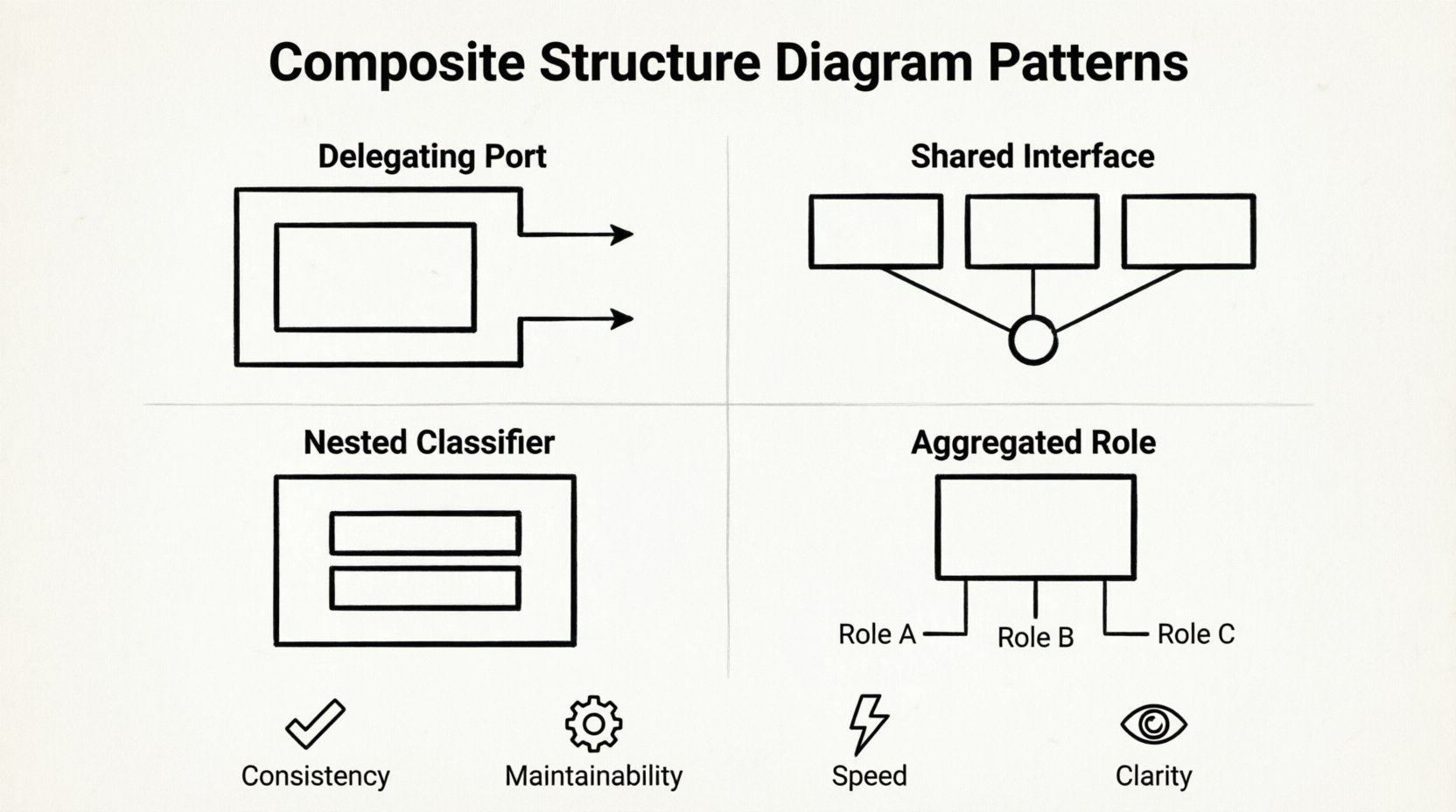
- Consistency: Every team member understands the structure because they have seen it before.
- Maintainability: If the internal logic of a standard module changes, the update applies to all instances of that pattern.
- Speed: Design time is reduced significantly when pre-defined structures are available.
- Clarity: Complex systems become easier to read when standard patterns are used consistently.
When implementing reuse, the focus shifts from defining the *what* to defining the *how*. The pattern defines the interface requirements and the internal arrangement, allowing the specific implementation details to vary.
🛠️ Key Patterns for Reuse
Several specific patterns emerge frequently in Composite Structure Diagrams. These patterns address common architectural needs such as delegation, aggregation, and interface sharing.
1. The Delegating Port Pattern
This pattern is used when a composite needs to expose functionality provided by one of its internal parts without exposing the internal part itself. It acts as a proxy for communication.
- Structure: The composite has a port. An internal part has a port. A connector links the composite port to the internal part port.
- Usage: Use this when the internal part is an implementation detail. The composite shields the rest of the system from knowing about the specific part.
- Benefit: Decouples the external interface from the internal implementation.
2. The Shared Interface Gateway
In complex systems, multiple parts often need to communicate using the same protocol or set of operations. Instead of creating unique connectors for every pair of parts, a shared interface pattern can be utilized.
- Structure: Multiple parts implement the same interface. They connect to a common gateway or bus within the composite structure.
- Usage: Ideal for logging, event handling, or configuration management where many components need access to the same resource.
- Benefit: Reduces the number of direct connections between parts, simplifying the internal graph.
3. The Nested Classifier Hierarchy
Some structures are too complex to be represented at a single level of detail. The nested classifier pattern allows a part to be a composite itself.
- Structure: A part in the parent composite contains its own internal structure definition.
- Usage: Use this when a component has significant internal complexity that requires separate visualization.
- Benefit: Allows for a high-level overview without losing the ability to drill down into specific sub-structures.
4. The Aggregated Role Pattern
When a part plays multiple roles within a composite, the Aggregated Role pattern clarifies these relationships.
- Structure: A single part is connected to multiple ports via different connectors, each with a distinct role label.
- Usage: Useful for components that act as both a controller and a data source simultaneously.
- Benefit: Prevents ambiguity regarding the function of a specific internal component.
📊 Comparing Pattern Strategies
To assist in selecting the appropriate pattern for a specific scenario, consider the following comparison. This table outlines the primary use cases and complexity levels associated with each pattern.
| Pattern Name | Primary Use Case | Complexity | Reusability Score |
|---|---|---|---|
| Delegating Port | Hiding internal implementation details | Low | High |
| Shared Interface Gateway | Centralized resource access (e.g., logging) | Medium | Very High |
| Nested Classifier | Deep structural decomposition | High | Medium |
| Aggregated Role | Multi-functional components | Medium | Medium |
The table highlights that the Shared Interface Gateway offers the highest reusability score. This is because a logging or configuration module is often required across many different parts of a system. Implementing this pattern once and referencing it multiple times yields significant time savings.
⚙️ Implementation Workflow
Integrating these patterns into a design process requires a systematic approach. The following steps outline how to move from abstract concept to concrete diagram structure.
- Analyze Requirements: Identify recurring functional requirements across the system. Look for authentication, data storage, or communication protocols that appear in multiple places.
- Define the Standard: Create a base Composite Structure Diagram for the identified pattern. Ensure all ports and interfaces are clearly defined.
- Abstract the Interface: Ensure the pattern relies on interfaces rather than concrete classes where possible. This allows for flexibility in implementation.
- Apply to Instances: When designing new components, reference the standard pattern instead of drawing the structure from scratch.
- Validate Connectivity: Check that the connectors between the pattern and the rest of the system match the expected roles and interfaces.
- Document Variations: If a pattern needs slight modification for a specific instance, document the deviation clearly to maintain future understanding.
Following this workflow ensures that reuse is intentional rather than accidental. It prevents the creation of fragmented structures that look similar but function differently.
🔧 Maintenance and Evolution
Once patterns are established, they must be maintained. Software systems evolve, and the structures within them must adapt. A rigid adherence to old patterns can hinder progress, while constant changes can lead to chaos.
- Version Control for Models: Treat the diagram structures like code. Keep track of changes to the standard patterns. If a pattern changes, all instances must be updated.
- Impact Analysis: Before modifying a standard pattern, analyze which parts of the system rely on it. Changing a shared interface can ripple through the entire architecture.
- Deprecation Strategy: If a pattern is no longer suitable, mark it as deprecated. Do not delete it immediately, as legacy systems may still reference it.
- Refactoring Cycles: Periodically review the patterns. As the system grows, some patterns may become too complex or too specific. Generalize them if necessary.
Maintenance is an ongoing responsibility. It requires discipline to ensure that the reusable structures remain accurate representations of the system’s reality.
🔗 Integration with Other Diagrams
A Composite Structure Diagram does not exist in isolation. It works in concert with other UML diagrams to provide a complete picture of the system. Reusing structures in CSDs can streamline the creation of these related diagrams.
- Class Diagrams: The classes in a Class Diagram correspond to the classifiers in the Composite Structure Diagram. Reusing structure ensures that the internal composition matches the class definitions.
- Sequence Diagrams: When creating interaction flows, the ports defined in the CSD become the lifelines. A consistent port naming convention helps in writing sequence diagrams faster.
- Deployment Diagrams: The physical placement of components can be mapped from the internal structure. If a part is a separate service, it moves to a different node in the deployment view.
Consistency across these diagram types reduces cognitive load for stakeholders. If a component is named and structured one way in the Composite Structure Diagram, it should appear similarly in the Class and Sequence Diagrams.
🚧 Common Challenges and Solutions
Even with a solid strategy, challenges arise when implementing patterns. Recognizing these issues early can prevent significant rework.
Challenge 1: Over-Abstraction
Attempting to make a pattern too generic can make it useless. If a pattern is defined without enough context, it may not solve the specific problem at hand.
- Solution: Balance generality with specificity. Define the core pattern broadly but include extension points for specific requirements.
Challenge 2: Circular Dependencies
Complex reuse can sometimes introduce circular dependencies between parts. This occurs when Part A requires Part B, and Part B requires Part A.
- Solution: Use interfaces to break the cycle. Ensure that the dependencies are defined at the interface level rather than the concrete part level.
Challenge 3: Naming Conflicts
When reusing structures, part names can become ambiguous. A part named “Data” might mean different things in different contexts.
- Solution: Adopt a strict naming convention. Include the context in the name, such as “UserDataPart” or “SystemDataPart”.
📈 Measuring the Impact of Reuse
To justify the effort in establishing and maintaining these patterns, it is useful to measure their impact. Quantitative and qualitative metrics can demonstrate value.
- Diagram Creation Time: Track how long it takes to create a new composite structure. Reuse should reduce this time over iterations.
- Error Rate: Monitor the number of structural inconsistencies found during reviews. Standardized patterns reduce confusion.
- Modification Cost: Estimate the effort required to update the system when a core component changes. Reuse should localize these changes.
- Stakeholder Understanding: Gather feedback from non-technical stakeholders. Consistent patterns often lead to better comprehension of the system.
🌐 Future-Proofing Your Architecture
Designing with reuse in mind prepares the system for future changes. Technology stacks evolve, and requirements shift. A flexible pattern-based approach allows the architecture to adapt without collapsing.
By focusing on the structural relationships rather than specific implementations, the diagrams remain valid even when the underlying technology changes. The pattern describes the interaction, not the code. This distinction is vital for long-term design integrity.
Architects should document the rationale behind each pattern. Why was the Delegating Port chosen over a direct connection? Why was this interface shared? These notes become part of the architectural record, guiding future decisions.
🎯 Final Thoughts on Structural Efficiency
The journey toward efficient system design is paved with patterns. The Composite Structure Diagram provides the canvas, but the patterns provide the brushstrokes that create order from complexity. By reusing common structures, teams can focus on solving unique business problems rather than reinventing the wheel for every module.
Adopting these strategies requires discipline and a commitment to consistency. It means resisting the urge to customize every diagram to the last detail. Instead, it means trusting the standard patterns to handle the common cases, leaving room for innovation where it truly matters. As systems grow in size and scope, the value of these reusable structures becomes increasingly apparent.
Start by identifying one recurring pattern in your current projects. Define it clearly. Apply it to a new component. Evaluate the results. From this small step, a more robust and efficient modeling practice can emerge. The goal is not just to draw diagrams, but to design systems that are clear, maintainable, and ready for the future.