


In the evolving landscape of software architecture, clarity remains paramount. As systems grow in complexity, the need for precise internal modeling becomes critical. The Composite Structure Diagram (CSD) offers a unique lens into the internal organization of a classifier. While often overshadowed by class or sequence diagrams in general discussions, its utility in defining boundaries, interfaces, and internal collaborations persists as a cornerstone for robust design.
This guide explores the practical applications, structural nuances, and future trajectory of composite structure diagrams within contemporary engineering practices. We examine how these models support distributed systems, microservices, and rigorous documentation standards without relying on specific tooling.
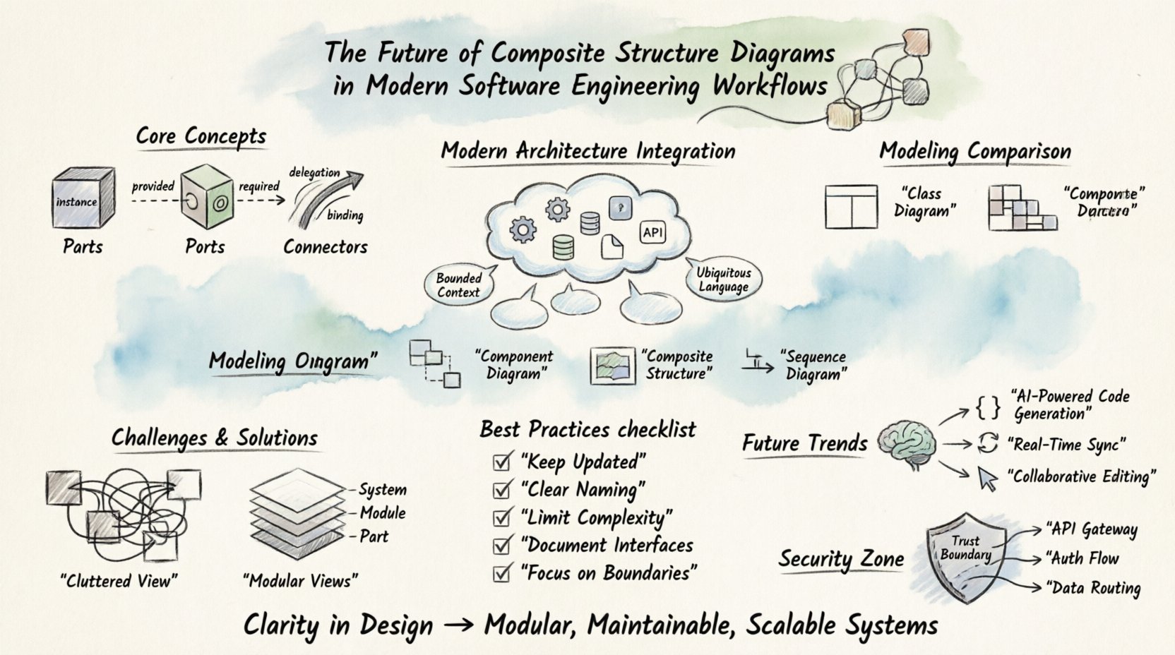
🧩 Understanding the Core Concepts
A composite structure diagram depicts the internal structure of a class or component. It reveals how parts are assembled to form a whole. Unlike a class diagram that focuses on attributes and methods, this model focuses on the arrangement of internal components. This distinction is vital when the internal logic is more complex than a simple data structure.
Parts: The Building Blocks
Parts represent instances of classifiers within the structure. They are the tangible building blocks of the composite entity. Each part has a specific role within the system.
- Named Instances: Specific parts can be identified by name, allowing for distinct references within the diagram.
- Typed by Classifier: Every part must be associated with a specific classifier type, ensuring type safety and logical consistency.
- Defined Lifecycles: The lifecycle of a part is often tied to the lifecycle of the composite structure, though it can be more granular.
Ports: The Interaction Faces
Ports define the interaction points of a part. They are the faces through which a part communicates with the outside world or other parts. Without ports, parts would be isolated islands of logic.
- Provided Interfaces: These indicate services or functions that the part makes available to others.
- Required Interfaces: These indicate the services or functions the part needs from its environment.
- Contract Definitions: Ports serve as the boundary for contracts, defining exactly what is expected and delivered.
Connectors: The Communication Paths
Connectors link parts to ports. They establish the communication paths and data flow between internal components.
- Delegation Connectors: These pass requests from the composite structure to an internal part.
- Binding Connectors: These bind a required interface to a provided interface.
- Linking Interfaces: These establish direct links between ports without intermediate interfaces.
🏗️ Integration with Modern Architectures
Modern software engineering has shifted towards distributed systems. Microservices, event-driven architectures, and cloud-native patterns demand clear boundaries. The composite structure diagram helps visualize these boundaries effectively.
Microservices and Service Boundaries
When designing a microservice, it is essential to understand its internal composition. A CSD can model the internal components of a service, showing how it handles requests before delegating to other services.
- Service Boundaries: Clearly delineate where one service ends and another begins.
- API Contracts: Define the external interfaces of the service using provided and required ports.
- Data Ownership: Visualize which parts manage specific data domains, reducing coupling.
Domain Driven Design (DDD) Alignment
DDD emphasizes the importance of the Bounded Context. Composite structures align well with this concept by modeling the internal structure of a bounded context.
- Ubiquitous Language: The diagram uses the same terminology as the code and domain experts.
- Context Mapping: Internal parts can represent subdomains, making the relationship between them explicit.
- Strategic Design: Helps identify where the system boundary should be drawn for maximum cohesion.
📊 Comparison of Modeling Techniques
Selecting the right diagram type is crucial for effective communication. Different diagrams serve different purposes. The table below outlines how the composite structure diagram fits among other common modeling techniques.
| Technique | Primary Focus | Granularity | Typical Usage |
|---|---|---|---|
| Class Diagram | Attributes & Methods | Static | Object-Oriented Design |
| Component Diagram | Deployment & Dependencies | High | System Architecture |
| Composite Structure | Internal Parts & Interfaces | Detailed | Implementation & Refactoring |
| Sequence Diagram | Behavior & Timing | Dynamic | Interaction Flows |
While a class diagram describes what a class contains, the composite structure diagram describes how the class is built internally. This distinction is often overlooked but is critical for complex implementations.
⚙️ Challenges in Maintenance and Adoption
Despite the benefits, maintaining composite structure diagrams presents specific challenges. Teams must balance the value of documentation against the cost of maintenance.
Complexity Management
As systems grow, diagrams can become cluttered. A single composite structure can contain hundreds of parts and connections. Visual complexity can hinder understanding.
- Abstraction Levels: Use different views for different stakeholders. High-level views show major parts; low-level views show detailed interfaces.
- Modularity: Break large diagrams into smaller, manageable sub-structures.
- Standardization: Enforce naming conventions and layout rules to reduce cognitive load.
Alignment with Agile Workflows
Agile methodologies prioritize working software over comprehensive documentation. However, this does not mean documentation is unnecessary. The key is just-in-time documentation.
- Iterative Updates: Update diagrams only when the internal structure changes significantly.
- Code as Source of Truth: Ensure the diagram reflects the current code state, or vice versa.
- Automation: Use reverse engineering tools to generate diagrams from existing codebases.
✅ Best Practices for Implementation
To maximize the value of composite structure diagrams, teams should adhere to specific best practices. These guidelines help maintain clarity and utility over time.
- Keep Diagrams Updated: Outdated diagrams are more harmful than no diagrams. They create false expectations.
- Use Clear Naming Conventions: Names should be self-explanatory. Avoid abbreviations that are not widely understood.
- Limit Complexity per View: Do not attempt to show every detail in a single diagram. Use multiple views.
- Document Interfaces: Clearly document the contracts exposed by ports. This aids in integration testing.
- Focus on Boundaries: Emphasize where the system boundary lies. This helps in defining security and access control zones.
- Integrate with Testing: Use the diagram to identify integration points for test cases.
- Review Regularly: Include diagram review in code review processes to ensure structural integrity.
🔮 The Path Forward: Automation and AI
The future of modeling is tied closely to automation and intelligent systems. The manual effort required to maintain detailed diagrams is a bottleneck that technology aims to resolve.
Code Generation and Synchronization
Forward engineering allows models to generate code stubs. Reverse engineering allows code to update models. This bidirectional flow reduces manual error.
- Schema Generation: Automatically generate data schemas from internal part definitions.
- Interface Boilerplate: Generate interface definitions based on port requirements.
- Sync Mechanisms: Implement hooks that update the diagram when code changes are committed.
AI-Assisted Modeling
Artificial intelligence can assist in suggesting structural improvements or identifying inconsistencies.
- Pattern Recognition: AI can suggest standard architectural patterns based on the current structure.
- Optimization: Algorithms can analyze dependencies to suggest refactoring opportunities.
- Visualization: AI can automatically layout complex diagrams to improve readability.
Real-Time Collaboration
Modern workflows require real-time updates. Cloud-based modeling platforms allow multiple architects to view and edit structures simultaneously.
- Live Editing: Changes are reflected immediately for all team members.
- Version Control: Diagrams are treated as code, stored in version control systems.
- Commenting: Inline comments allow for discussion directly on the structural elements.
🛡️ Security and Access Control Implications
Security architecture is often an afterthought. Composite structure diagrams can help integrate security into the design phase by visualizing access boundaries.
Defining Trust Zones
Parts within a diagram can represent different trust zones. This helps in defining where authentication and authorization must occur.
- Internal vs External: Clearly distinguish between internal parts and external consumers.
- Privileged Parts: Highlight parts that require elevated privileges to access.
- Data Flow: Trace how sensitive data moves between parts to identify exposure points.
API Gateway Modeling
In microservices, the API gateway is a critical component. CSD can model the gateway’s internal logic for routing and validation.
- Routing Logic: Show how requests are directed to specific internal parts.
- Validation: Indicate where input validation occurs before reaching business logic.
- Transformation: Model data transformation steps required for different clients.
📝 Moving Forward with Structural Clarity
Modeling is not an end goal in itself. It is a tool for understanding and communication. Teams should adopt practices that aid comprehension without burdening the workflow. The composite structure diagram provides a necessary level of detail that other diagrams often omit.
By focusing on internal organization, interfaces, and parts, engineers can build systems that are modular, maintainable, and scalable. The shift towards more granular modeling supports the transition from monolithic architectures to distributed, resilient systems. As automation tools mature, the effort required to maintain these models will decrease, making them an even more viable option for modern teams.
The goal is not perfection in documentation, but clarity in design. When the structure is understood, the code becomes easier to write, test, and refactor. This approach ensures that the architecture remains aligned with the business requirements over time.