


Software architecture relies on clear visual representations to convey how complex systems function internally. Among the Unified Modeling Language (UML) tools, the Composite Structure Diagram (CSD) offers a granular view of an object’s internal organization. This diagram type moves beyond the external behavior to reveal the internal mechanics, specifically focusing on how parts interact, connect, and fulfill responsibilities.
When designing robust systems, understanding the internal structure is critical. It allows architects to define clear boundaries, manage interfaces, and ensure that components communicate effectively without tight coupling. This guide explores the core elements of this diagram type, providing a detailed look at parts, ports, and connectors.
What is a Composite Structure Diagram? 🧩
A Composite Structure Diagram describes the internal structure of a classifier, such as a class or an interface. While a Class Diagram shows attributes and methods, the Composite Structure Diagram zooms in to show the internal components that make up that class. It is particularly useful for showing:
- Internal composition: How a complex object is built from smaller parts.
- Collaboration: How these internal parts work together to provide functionality.
- Interfaces: The specific points of interaction between the internal structure and the external environment.
This level of detail is essential for systems where the internal logic dictates the overall stability and scalability. By visualizing the internal structure, teams can identify potential bottlenecks or areas where responsibilities overlap.
Core Elements of the Diagram 🔍
Three primary elements form the foundation of this modeling approach. Each plays a distinct role in defining the behavior and connectivity of the system.
1. Parts 🧱
A Part represents an instance of a classifier within the composite structure. It is essentially a component that exists inside the main structure. Parts define the internal composition of the classifier.
- Definition: A part is a named occurrence of a type. For example, if you have a \”Car\” class, a \”Engine\” part within that class represents a specific engine instance.
- Multiplicity: Parts can have multiplicity, indicating how many instances exist. A single car might have one engine (1) or a fleet of cars might have many engines (*).
- Lifecycle: Parts often have a lifecycle tied to the composite. When the composite object is created, the parts are created. When the composite is destroyed, the parts are typically destroyed as well.
2. Ports 🌐
Ports act as interaction points. They define where a part can communicate with other parts or with the outside world. Ports are crucial for encapsulation, as they hide the internal details of a part and expose only what is necessary.
- Provided Interfaces: A port can offer services. Other parts can use these services by connecting to the provided interface.
- Required Interfaces: A port can demand services. The part needs these services to function, and the interface must be satisfied by a connector.
- Encapsulation: Ports ensure that internal parts do not interact directly with each other in an uncontrolled manner. All interaction must go through a defined port.
3. Connectors 🔗
Connectors define the communication paths between ports. They link a required interface to a provided interface, establishing a contract for data or control flow.
- Binding: A connector binds a specific port to a specific interface. It ensures that the data types and protocols match.
- Flow Direction: Connectors often imply a direction of data flow, though they can be bidirectional depending on the interface definition.
- Aggregation: Connectors can represent aggregation relationships, showing how parts are held together within the structure.
Deep Dive: Parts and Roles 🧠
Understanding the distinction between a Part and a Role is vital for accurate modeling. While they often look similar, their semantic meaning differs significantly in complex systems.
Part vs. Role Comparison
Parts represent the physical or logical components inside the structure. Roles represent the way a part interacts within a specific context. A single part might play multiple roles at different times.
| Feature | Part | Role |
|---|---|---|
| Definition | An instance of a classifier within the composite. | A named interaction point for a part. |
| Focus | Focuses on the entity itself and its lifecycle. | Focuses on the behavior or interface provided. |
| Multiplicity | Defines how many instances exist. | Defines how the instance participates in a relationship. |
| Visibility | Visible as a structural component. | Visible as an interaction capability. |
Consider a database system. The \”Database\” is the Part. However, within that database, the \”Storage Engine\” acts as a Role that provides specific read/write capabilities. The same database might have different roles depending on whether it is acting as a master or a replica.
Ports: The Interface Contracts 📡
Ports are the gatekeepers of the composite structure. They enforce the boundary between the internal logic and external requests. This separation is key to maintaining modularity.
Provided vs. Required Interfaces
Every port must specify the type of interaction it supports.
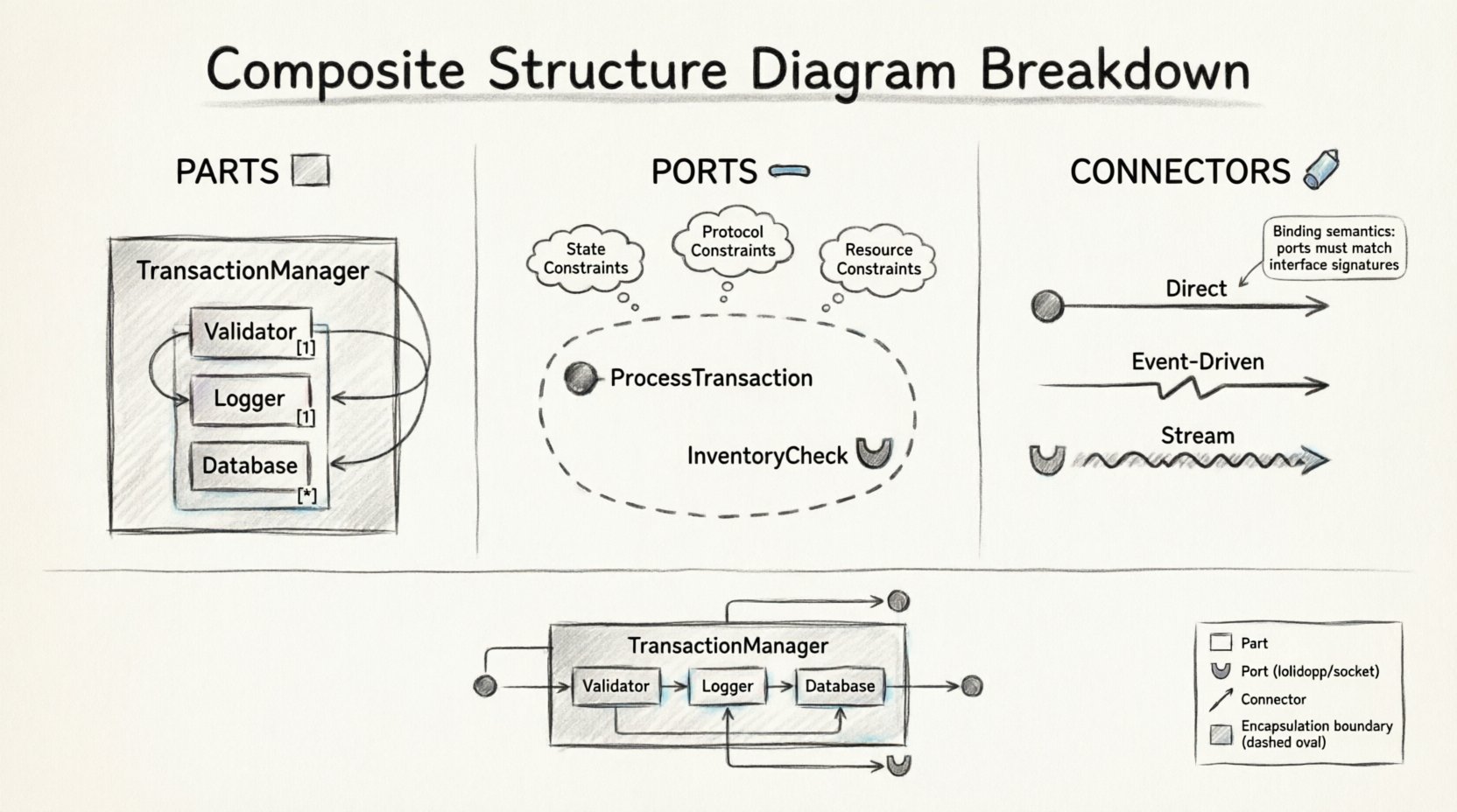
- Provided Interface (Lollipop Symbol): This indicates that the part offers a service. For example, a \”PaymentProcessor\” part might provide a \”ProcessTransaction\” interface. Other parts can connect to this port to trigger the transaction.
- Required Interface (Socket Symbol): This indicates that the part needs a service. For example, the \”OrderManager\” part might require a \”InventoryCheck\” interface. It cannot function until this requirement is met by a connector.
Interaction Constraints
Ports are not just open doors; they often have constraints. These constraints define the conditions under which the interface can be used.
- State Constraints: A port might only be available if the part is in a specific state. For instance, a \”WritePort\” might be locked if the system is in \”Read-Only\” mode.
- Protocol Constraints: Some ports require a specific sequence of messages. The diagram can specify that a connection must be established before data transfer begins.
- Resource Constraints: Certain ports may only be active when specific resources (like memory or network bandwidth) are available.
Connectors and Data Flow 🔄
Connectors are the wires that power the system. They define how information moves between the internal parts. Without connectors, the parts are isolated and cannot collaborate.
Types of Connections
Not all connections are created equal. The diagram should reflect the nature of the data flow.
- Direct Connections: A straightforward link between two ports. This is common for simple method calls or synchronous data transfers.
- Event-Driven Connections: These connections trigger actions based on events. One part emits an event, and another part listens via its required port.
- Stream Connections: These are used for continuous data flows, such as log streams or video feeds, rather than discrete messages.
Binding Semantics
Binding refers to the specific attachment of a connector to a port. It defines the protocol and the data format.
- Explicit Binding: The connection is explicitly defined in the diagram. This is best for critical paths where reliability is paramount.
- Implicit Binding: The system infers the connection based on naming conventions or interface types. While convenient, this can lead to confusion in complex diagrams.
Practical Application: A Financial System Example 💰
To illustrate how these elements come together, consider a generic financial transaction system.
System Components
- TransactionManager: The main composite structure.
- Validator: A part responsible for checking input data.
- Logger: A part responsible for recording events.
- Database: A part responsible for storing records.
Internal Structure
The TransactionManager composite contains the Validator, Logger, and Database as parts. The Validator part has a required port for \”DataFormat\” and a provided port for \”ValidationResult\”. The Database part requires a \”WriteAccess\” port and provides a \”QueryResult\” port.
The TransactionManager connects the Validator’s \”ValidationResult\” port to its own internal processing logic. It also connects the Logger’s required port to the TransactionManager’s provided logging interface. This ensures that every transaction is logged automatically without the TransactionManager needing to know the internal details of the Logger.
Benefits of this Approach
- Decoupling: Changes to the Logger do not affect the Validator.
- Clarity: The flow of data is explicit and visible.
- Maintainability: New parts can be added as long as they adhere to the defined interfaces.
Common Mistakes and Pitfalls ⚠️
Creating these diagrams can be challenging. Teams often fall into traps that reduce the value of the model.
Overcomplicating the Diagram
Adding too many internal parts can make the diagram unreadable. If a class is simple, a Class Diagram is often sufficient. Reserve this diagram for complex structures where internal collaboration is key.
Ignoring Interface Contracts
Defining ports without specifying the interface leads to ambiguity. Always define the exact methods or events that a port provides or requires. This prevents integration errors later.
Confusing Parts with Classes
A Part is an instance of a Class within a specific context. Confusing the two can lead to incorrect assumptions about lifecycle and ownership. Remember that parts are owned by the composite.
Neglecting Lifecycle Management
If parts are created and destroyed at different rates than the composite, the diagram should reflect this. Assuming all parts die when the parent dies can lead to resource leaks or orphaned data.
Relationship with Other Diagrams 📊
This diagram does not exist in isolation. It complements other UML diagrams to provide a complete picture of the system.
Class Diagram
The Class Diagram defines the static structure. The Composite Structure Diagram defines the internal arrangement of those classes. Use the Class Diagram for high-level design and the Composite Structure Diagram for detailed implementation planning.
Sequence Diagram
Sequence Diagrams show the flow of messages over time. Composite Structure Diagrams show where those messages go. They work well together to validate that the internal structure supports the required behavior.
Component Diagram
Component Diagrams are similar but operate at a higher level of abstraction. They focus on deployable units. Composite Structure Diagrams focus on the internal logic of a specific unit.
When to Use This Diagram 🎯
Not every system requires this level of detail. Use it when:
- Complexity is High: The internal logic is too complex for a single class definition.
- Interfaces are Critical: The system relies heavily on strict interface contracts.
- Collaboration is Key: The success of the system depends on how internal parts interact.
- Performance is a Concern: You need to analyze data flow and potential bottlenecks within the object.
Best Practices for Documentation 📝
To ensure the diagram remains useful over time, follow these guidelines.
- Keep it Updated: As the code changes, the diagram must change. An outdated model is worse than no model.
- Use Consistent Notation: Stick to standard symbols for ports and connectors. Consistency aids understanding.
- Document Interfaces: Write clear descriptions for every interface. Don’t rely on names alone.
- Limit Scope: Focus on one composite at a time. If the system is too large, break it down into sub-structures.
- Review Regularly: Include the diagram in design reviews. Fresh eyes often catch logical errors.
Technical Considerations 🛠️
When implementing the logic described in these diagrams, several technical factors come into play.
Memory Management
Parts often consume memory. Understanding the lifecycle helps in managing memory allocation and deallocation. Explicitly defining ownership prevents memory leaks.
Thread Safety
If parts operate concurrently, ports must be thread-safe. The diagram should indicate if synchronization mechanisms are required for specific ports.
Error Handling
Connectors can fail. The structure should account for error propagation. Define how a failure in one part affects the others through the defined interfaces.
Final Thoughts on Structural Clarity ✨
Visualizing internal structure is a powerful tool for system design. It transforms abstract logic into a tangible map that teams can navigate. By focusing on parts, ports, and connectors, architects can build systems that are modular, maintainable, and robust.
The goal is not just to draw a diagram, but to think through the interactions. Every connector represents a decision about how data flows. Every port represents a decision about what is exposed. Every part represents a decision about responsibility.
As systems grow in complexity, the need for this level of detail increases. It provides the clarity necessary to manage change without breaking the foundation. By adhering to these principles, teams can ensure their architecture stands the test of time.
Continuously refining these models ensures that the design remains aligned with the implementation. This alignment reduces technical debt and accelerates development. It is a practice that pays dividends throughout the lifecycle of the software.