


When students begin modeling complex software architectures, the standard class diagram often feels insufficient. It shows relationships between objects, but it fails to reveal how those objects are built internally. This is where the Composite Structure Diagram becomes essential. It provides a window into the internal composition of classifiers. This guide addresses the most common inquiries encountered during undergraduate software engineering projects.
Understanding this diagram type requires precision. It bridges the gap between logical design and physical structure. Below, we explore the definitions, components, and practical applications necessary for academic success.
What is a Composite Structure Diagram? 🧩
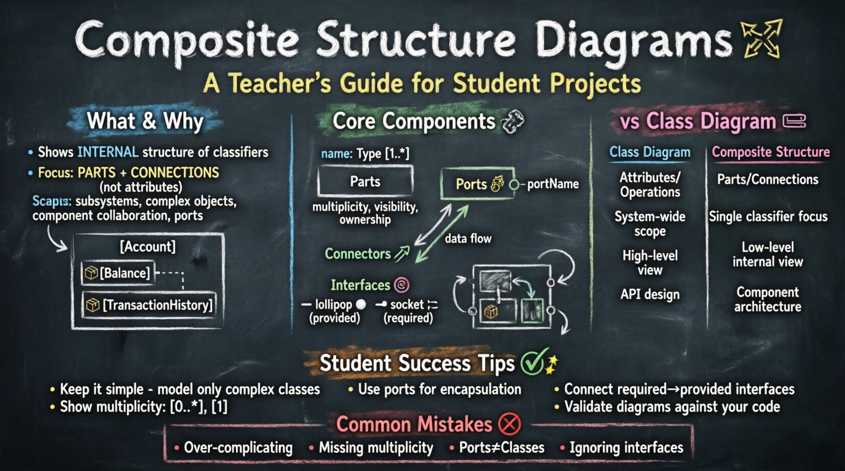
A Composite Structure Diagram is a type of structural diagram in the Unified Modeling Language (UML). It depicts the internal structure of a classifier. Unlike a class diagram, which focuses on attributes and operations, this diagram focuses on parts and their connections. It answers the question: What makes up this element?
For undergraduate projects, this diagram is often used to model:
- The internal architecture of a subsystem
- The composition of a complex object
- The collaboration between internal components
- The exposure of interfaces through ports
It is particularly useful when the internal organization of a class matters more than its external behavior. For instance, if you are designing a banking system, you might need to show how a Account object is composed of a Balance part and a TransactionHistory part.
Core Components Explained 🔧
To create a valid diagram, you must understand the building blocks. Each element serves a specific purpose in defining the internal structure. Ignoring these distinctions leads to inaccurate models.
1. Parts 📦
Parts represent the internal objects that make up a classifier. They are often shown as rectangles inside the larger classifier rectangle. Each part has a name and a type. The name indicates the role the part plays within the whole.
Key characteristics of parts include:
- Multiplicity: You can specify how many instances of a part exist (e.g., 1, 0..*, 1..3).
- Visibility: Public, private, protected, or package visibility can be applied to parts.
- Ownership: Parts are owned by the classifier. If the classifier is destroyed, the parts are typically destroyed as well, unless they are shared.
2. Ports 🔌
Ports are interaction points. They define how a classifier communicates with the outside world or with other parts within its own structure. Ports are essentially named interaction points on the boundary of a classifier.
Why are ports important? They encapsulate interaction details. Instead of connecting directly to a class, you connect to a port. This allows the internal implementation to change without affecting the external connections.
3. Connectors 🔗
Connectors link parts to ports. They represent the flow of information between components. A connector can link two parts within the same classifier, or it can link a part to an external classifier.
Connectors ensure that data flows correctly. They define the specific interface required for communication. Without connectors, parts remain isolated islands within the structure.
4. Interfaces and Provided/Required Roles 🎯
Interfaces define a contract. A part might require a specific interface to function. A part might provide an interface to be used by others.
- Provided Interface: The part offers a service. This is often drawn as a lollipop symbol.
- Required Interface: The part needs a service. This is often drawn as a socket symbol.
Mapping these correctly is crucial for showing dependencies. If a part requires an interface, it cannot function without an external provider or an internal implementation.
Frequently Asked Questions ❓
Students frequently struggle with the nuances of this diagram. The following Q&A section addresses specific technical concerns.
Q1: When should I use a Composite Structure Diagram instead of a Class Diagram? 🤔
Use a Class Diagram when you need to show the general structure of the system, including attributes, methods, and inheritance. Use a Composite Structure Diagram when you need to show the physical or logical composition of a specific class.
If your project involves:
- Complex aggregation where the internal arrangement matters
- Multiple components working together within a single object
- Need to specify how internal parts collaborate
Then the Composite Structure Diagram is the correct choice. It adds a layer of detail that a class diagram cannot provide.
Q2: How do I represent a one-to-many relationship in this diagram? 📊
You use multiplicity notation next to the part name. For example, if a Library class contains many Book parts, you would label the part as books: Book [0..*]. This indicates that the Library can have zero to many Book instances internally.
Ensure you distinguish between aggregation and composition:
- Composition: Strong ownership. The part cannot exist without the whole. Shown with a filled diamond.
- Aggregation: Weak ownership. The part can exist independently. Shown with an open diamond.
Q3: Can I show internal collaboration between parts? 🤝
Yes. This is a primary strength of the diagram. You can draw connectors between parts to show how they exchange data. For example, a Processor part might send data to a Memory part via a connector.
This visualization helps stakeholders understand the data flow within a system component. It clarifies which parts depend on which other parts for operation.
Q4: How do I handle interfaces on parts? ⚙️
Interfaces on parts are similar to ports. You can specify that a part provides a service or requires a service. You attach the interface symbol to the part.
Best practice suggests:
- Use provided interfaces for parts that act as servers.
- Use required interfaces for parts that act as clients.
- Connect required interfaces to provided interfaces using connectors.
This creates a clear contract between internal components.
Composite Structure vs Class Diagram 🆚
Confusion often arises between these two diagram types. While both deal with structure, their focus differs significantly. A comparison table helps clarify the distinction.
| Feature | Class Diagram | Composite Structure Diagram |
|---|---|---|
| Focus | Attributes and Operations | Internal Parts and Connections |
| Scope | System-wide structure | Internal structure of a single classifier |
| Components | Classes, Interfaces, Associations | Parts, Ports, Connectors, Interfaces |
| Detail Level | High-level logical view | Low-level physical/logical view |
| Use Case | Database schema, API design | Component architecture, internal logic |
Understanding this table ensures you select the right tool for your documentation. Do not use a Composite Structure Diagram for the entire system architecture unless the project specifically requires deep internal analysis.
Common Student Mistakes 🚫
Even experienced modelers make errors. Identifying common pitfalls helps improve the quality of your undergraduate project deliverables.
- Over-complication: Trying to model every single class internally. This creates clutter. Focus on complex classes only.
- Missing Multiplicity: Forgetting to specify how many parts exist. This leaves the design ambiguous.
- Confusing Ports with Classes: Ports are interaction points, not full classes. Do not give them attributes unless necessary.
- Ignoring Interfaces: Failing to show which parts require which services. This hides dependencies.
- Incorrect Connectors: Connecting parts directly without using ports. This breaks encapsulation.
- Redundancy: Showing the same information in both a Class Diagram and a Composite Structure Diagram without adding value.
Review your diagrams against this list before submission. It ensures clarity and correctness.
Practical Application Examples 💡
To solidify understanding, consider specific scenarios used in academic projects.
Example 1: E-Commerce Order System 🛒
Imagine an Order classifier. It is composed of multiple CartItem parts. Each CartItem requires a Product interface to display details. The Order itself provides an Checkout interface to the user.
Internal flow:
- Order provides Checkout interface.
- Order contains many CartItems.
- CartItems require Product details.
- Connectors link CartItems to the Product service.
This shows how the order manages its internal state and interacts with external product data.
Example 2: Smart Home Hub 🏠
Consider a SmartHub classifier. It contains a NetworkManager part and a DeviceController part. The NetworkManager requires a Wi-Fi interface. The DeviceController provides a Control interface.
Internal flow:
- NetworkManager connects to external Wi-Fi via a port.
- DeviceController connects to NetworkManager via a connector.
- Hub exposes the Control interface to the user app.
This demonstrates the separation of concerns within a single complex object.
Example 3: Payment Gateway 💳
A PaymentProcessor classifier might contain a Validator part and a TransactionLogger part. The Validator requires a CardCheck interface. The TransactionLogger requires a Database interface.
This highlights the security and logging aspects of the payment process, showing that these are internal components necessary for the whole to function.
Tips for Academic Success 📚
When presenting this diagram in a project report, follow these guidelines to maximize clarity and marks.
- Keep it Simple: Only include parts that are relevant to the design decision. If a class is simple, a standard class diagram is sufficient.
- Use Consistent Naming: Ensure part names match the class names in the rest of your documentation. Inconsistency confuses the reader.
- Explain the Diagram: Do not assume the reader understands the notation. Provide a legend or explanation for complex connectors.
- Focus on Collaboration: Highlight how parts work together. This shows deep understanding of the system dynamics.
- Validate with Code: Ensure the structure you draw matches the implementation logic in your code. Discrepancies raise questions about your design process.
- Iterate: Draw the diagram, review it, and refine it. The first draft is rarely perfect.
By adhering to these practices, you demonstrate technical competence. You show that you understand not just what the system does, but how it is built.
Advanced Considerations 🔍
For students aiming for higher grades, consider these advanced topics.
Behavioral State Integration
While the Composite Structure Diagram is structural, it often works alongside State Machine Diagrams. You can indicate that a specific part changes state based on internal events. This adds depth to your modeling.
Refinement Levels
Complex systems may require multiple levels of detail. You might have a high-level Composite Structure Diagram for the whole system, and a detailed one for a specific critical class. Ensure you label these clearly to avoid confusion.
Real-World Constraints
In some projects, hardware constraints dictate the structure. If you are designing embedded software, the Composite Structure Diagram might reflect physical memory partitions or processor cores. This connects your model to the physical reality of the deployment.
Final Thoughts on Implementation 💬
Modeling internal structures is a critical skill for software engineers. It forces you to think about decomposition. It helps identify coupling and cohesion within your code. By mastering the Composite Structure Diagram, you gain a clearer view of your system’s anatomy.
Use this guide as a reference during your project lifecycle. Revisit the Q&A section if you encounter ambiguity. Ensure your diagrams are clean, accurate, and aligned with your codebase. This attention to detail distinguishes a good project from a great one.
Remember, the goal is clarity. If a stakeholder can look at your diagram and understand the internal mechanics of your system, you have succeeded.