


Systems Modeling Language, commonly known as SysML, serves as a specialized modeling language for systems engineering applications. It is designed to capture, analyze, and design complex systems. Whether you are working on aerospace projects, automotive designs, or software architecture, understanding the terminology is essential for clear communication among stakeholders. This guide breaks down the core vocabulary used within the discipline, helping you navigate the technical landscape with clarity.
Introduction to Systems Modeling Language 🏗️
SysML extends the Unified Modeling Language (UML) to better suit systems engineering needs. While UML focuses heavily on software, SysML addresses physical, information, and behavioral aspects of a system. It relies on a set of diagrams and elements that describe how a system functions. Mastering these terms allows engineers to create models that are both precise and understandable.
When starting out, it is common to encounter acronyms and specific definitions. This glossary covers the most frequent terms you will see in diagrams and documentation. The goal is to provide context, not just definitions, ensuring you understand how each term fits into the larger modeling effort.
Core Structural Elements 🔨
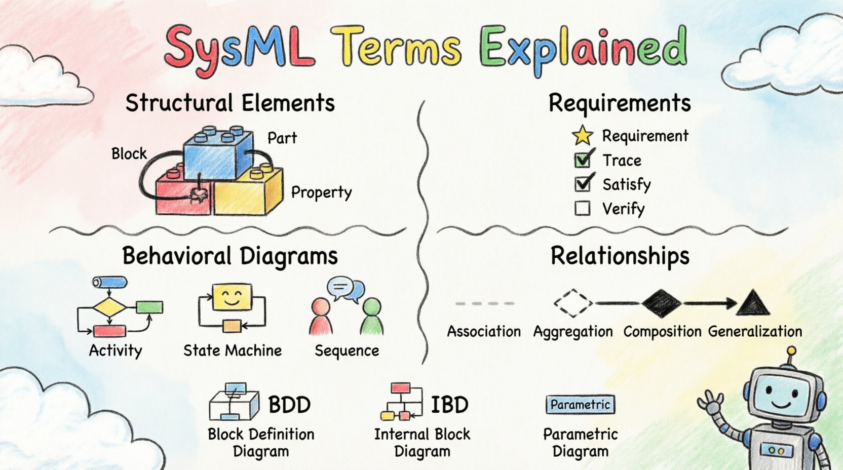
The structure of a system defines its physical or logical composition. In SysML, this is primarily described using Blocks. A Block represents a unit of structure, which can be a component, a part, or a system itself. It is the fundamental building block for defining what a system is made of.
- Block: A unit of structure with a defined interface and behavior. It encapsulates functionality and data.
- Part: A specific instance of a Block within a larger Block structure. It represents a component inside a system.
- Property: An attribute of a Block that describes data or characteristics. Properties can have types, such as integers or strings.
- Reference Property: A property that links to another Block instance. This creates a connection without ownership.
- Value Property: A property that holds a simple value, like a number or text, rather than a reference to another object.
Understanding the distinction between a Block and a Part is critical. A Block defines the type, while a Part defines the specific instance within a configuration. For example, an Engine might be a Block type, while a specific Engine inside a Car is a Part.
Understanding Requirements 📝
Requirements define what the system must do or the constraints it must satisfy. They are the foundation of validation and verification. In SysML, requirements are treated as first-class citizens, allowing them to be linked to other model elements.
- Requirement: A condition or capability that must be met. It is a specific element that can be traced to other model parts.
- Trace: A relationship indicating that one element is derived from or satisfies another. Commonly used to link requirements to design elements.
- Refine: A relationship indicating that one element provides more detail than another. For instance, a high-level requirement might be refined into a detailed specification.
- Satisfy: A relationship showing that a design element meets a specific requirement.
- Verify: A relationship indicating that a test case or activity confirms a requirement is met.
Effective requirement management ensures that the final product aligns with stakeholder needs. Using traces allows engineers to see the impact of a change. If a requirement changes, you can trace it down to see which design blocks or behaviors are affected.
Behavioral Diagrams 🔄
Behavior describes how a system acts over time or in response to events. SysML supports several diagram types to visualize this behavior. Each type serves a specific purpose depending on the complexity of the interaction.
Activity Diagrams
Activity diagrams focus on the flow of control and data. They are similar to flowcharts but include support for concurrent activities and object flows.
- Activity: A phase of computation that is triggered by an event. It is the main element in an activity diagram.
- Control Flow: The order in which activities occur. It dictates the sequence of execution.
- Object Flow: The movement of data or objects between activities. It shows what is produced and consumed.
- Input Pin: A point where an activity receives data or objects.
- Output Pin: A point where an activity sends data or objects.
State Machine Diagrams
State machines model the different states an element can be in and how it transitions between them based on events.
- State: A condition or situation during the life of an object where it performs some activity or waits for an event.
- Transition: The movement from one state to another. Transitions are triggered by events.
- Event: Something that happens at a specific time, causing a transition. It can be a signal, a call, a time delay, or a change in a condition.
- Guard Condition: A boolean expression that must be true for a transition to occur.
- History: A pseudo-state that remembers the last active sub-state of a composite state.
Sequence Diagrams
Sequence diagrams show interactions between objects over time. They are useful for understanding the flow of messages between parts of a system.
- Lifeline: Represents an instance of a class or object over time.
- Message: A communication from one object to another. It can be synchronous or asynchronous.
- Activation: The period during which an object is performing an action.
- Combined Fragment: A grouping of interactions, such as loops or optional sections.
Relationships and Connections 🔗
Relationships define how elements interact with one another. They are the glue that holds the model together. Selecting the correct relationship is vital for accurate modeling.
| Relationship | Description | Use Case |
|---|---|---|
| Association | A structural relationship indicating that objects of one type are connected to objects of another. | General connection without ownership. |
| Aggregation | A whole-part relationship where the part can exist independently of the whole. | Weak ownership, like a Department has Employees. |
| Composition | A strong whole-part relationship where the part cannot exist without the whole. | Strong ownership, like a House has Rooms. |
| Generalization | A parent-child relationship where the child inherits characteristics from the parent. | Class hierarchy or inheritance. |
| Realization | A relationship where one element implements the interface of another. | Interface implementation. |
Aggregation and Composition are often confused. The key difference lies in lifecycle management. In Composition, if the whole is destroyed, the parts are destroyed. In Aggregation, parts survive the destruction of the whole.
Constraints and Parameters 📏
Not all information can be captured visually. Constraints allow you to add rules that must be followed. Parameters help define the numerical values associated with a system.
- Constraint Block: A type of Block that represents a set of constraints. It can be applied to other model elements.
- Constraint Property: A property within a Constraint Block that represents a specific rule.
- Parameter Block: A Block used to define parameters for a system. It contains variables that can be set.
- Parameter Property: A property within a Parameter Block. These are often used for sizing or configuration.
- OCL (Object Constraint Language): A formal language used to specify constraints. It allows for precise mathematical definitions.
Using constraints ensures that the model adheres to physical laws or business rules. For example, a constraint might state that the weight of a vehicle cannot exceed a certain limit. Parameters allow you to run simulations by changing these values without altering the structure.
Summary of Key Diagrams 📊
To aid memory, here is a summary of the primary diagram types available in the language. Each diagram serves a distinct purpose in the modeling lifecycle.
| Diagram Type | Focus | Primary Elements |
|---|---|---|
| Block Definition Diagram (BDD) | Structure and Classification | Blocks, Relationships, Requirements |
| Internal Block Diagram (IBD) | Internal Structure | Parts, Properties, Flows |
| Requirement Diagram | Requirements Management | Requirements, Traces, Refinements |
| Use Case Diagram | Functional Requirements | Actors, Use Cases, Relationships |
| Activity Diagram | Behavioral Flow | Activities, Flows, Pools |
| State Machine Diagram | State Transitions | States, Transitions, Events |
| Sequence Diagram | Interaction Over Time | Lifelines, Messages, Activations |
| Parametric Diagram | Constraints and Equations | Constraints, Parameters, Variables |
Applying Terms in Real Scenarios 🌍
Knowing the definitions is only the first step. Applying these terms correctly requires understanding the workflow. A typical modeling process starts with requirements. You define what the system needs to do using the Requirement Diagram.
Next, you define the structure using the Block Definition Diagram. Here, you create Blocks for major components and define their relationships. You might use Composition to show that a system is made of sub-systems. Then, you use the Internal Block Diagram to show how these components connect internally. This is where you define data flows and interfaces.
Behavior is modeled next. If the system has complex logic, a State Machine Diagram is appropriate. If it involves processes, an Activity Diagram is better. Sequence diagrams help clarify interactions between specific parts during an operation.
Finally, constraints are added using Parametric Diagrams. This ensures that physical limits are respected. Throughout this process, traces link everything back to the original requirements. This ensures that no design element exists without a purpose defined by the stakeholders.
Common Pitfalls to Avoid ⚠️
Even experienced engineers can make mistakes when defining terms. Being aware of common errors helps maintain model quality.
- Overuse of Generalization: Do not create deep inheritance hierarchies unless necessary. It complicates the model.
- Mixing Structure and Behavior: Keep structural diagrams separate from behavioral diagrams. Do not put behavior logic inside a Block Definition Diagram.
- Ignoring Traces: Failing to link requirements to design elements makes verification difficult.
- Vague Constraints: Avoid writing constraints that are ambiguous. Use OCL for precision.
- Ignoring Parameters: Failing to define parameters can limit the ability to simulate or analyze the system.
Conclusion on Terminology 📚
Mastering the vocabulary of Systems Modeling Language is a journey. It requires practice and exposure to real models. By understanding the core terms like Blocks, Requirements, and Relationships, you build a solid foundation. This glossary provides a reference point, but true proficiency comes from application.
Consistency is key. Ensure that terms are used uniformly across the project. When stakeholders understand the language, communication improves. This reduces errors and accelerates development. The complexity of modern systems demands precise modeling, and accurate terminology is the tool that makes this possible.
As you continue to work with these concepts, refer back to this guide when you encounter unfamiliar terms. The relationships between elements are often more important than the definitions themselves. Focus on how the parts connect to form the whole. This holistic view is the essence of systems engineering.