


Systems engineering is fundamentally about managing complexity. When projects grow in scale, document-based approaches often fracture under the weight of changing specifications. A shift toward Model-Based Systems Engineering (MBSE) using the Systems Modeling Language (SysML) offers a structured path to align high-level stakeholder needs with concrete architectural decisions. This guide explores the logical flow from capturing requirements to defining a robust system architecture.
The transition is not merely about drawing diagrams; it is about establishing a coherent information model that ensures every architectural decision can be traced back to a specific need. This alignment reduces ambiguity, supports verification activities, and facilitates communication across diverse engineering disciplines.
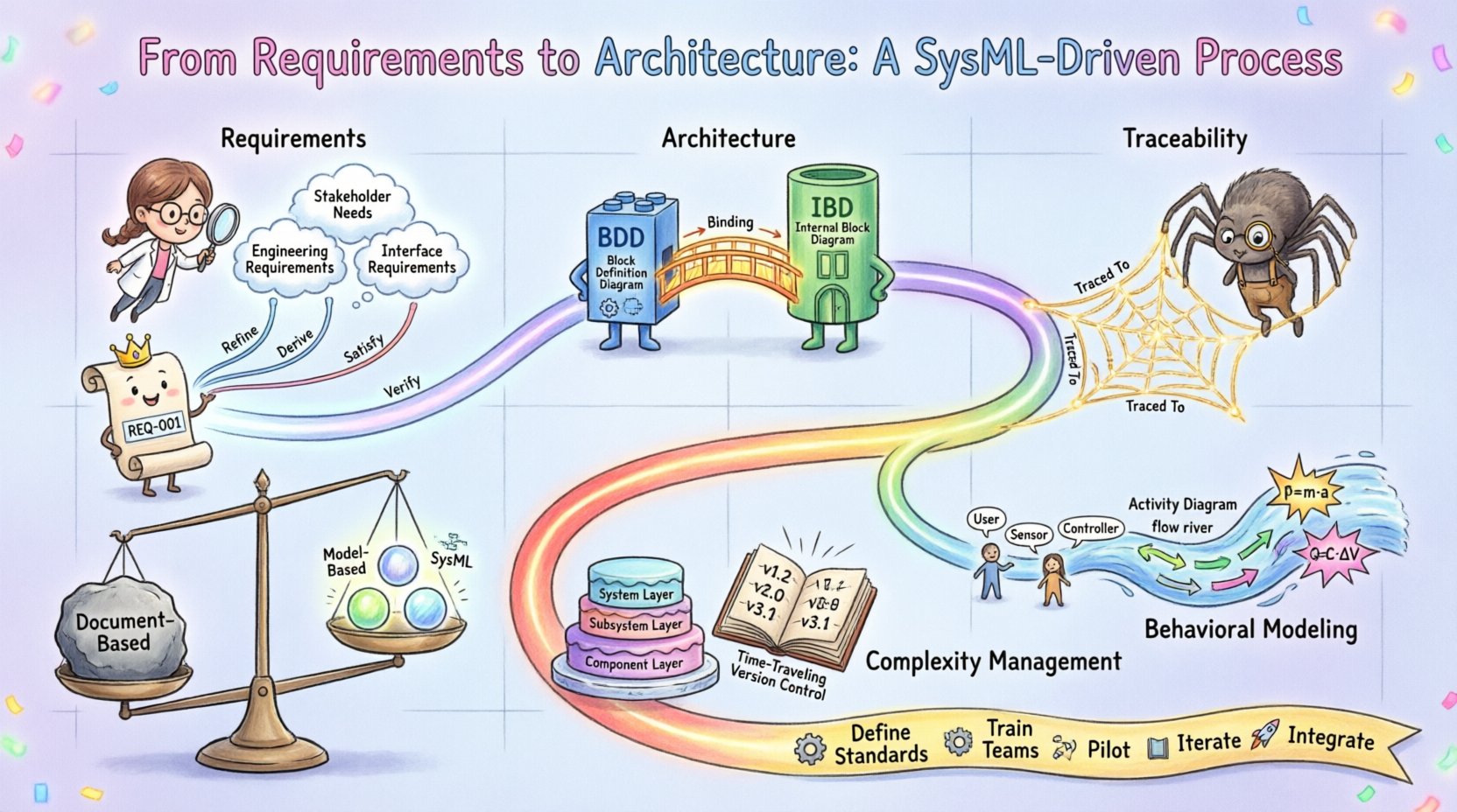
📋 Phase 1: Capturing and Structuring Requirements
The process begins with the collection of needs. In a SysML environment, requirements are not static text documents but dynamic objects within the model. They carry metadata, status, and relationships that allow for rigorous analysis.
🔹 Distinguishing Needs from Engineering Requirements
Not all inputs to the system are engineering requirements. The model must differentiate between:
Stakeholder Needs: High-level goals expressed in natural language, often from the client or end-user perspective.
Engineering Requirements: Precise, testable statements that define specific constraints or behaviors the system must exhibit.
Interface Requirements: Definitions of how the system interacts with external entities.
By categorizing these inputs early, the engineering team avoids conflating business goals with technical constraints. SysML provides a dedicated Requirement block type that allows for hierarchical structuring. A top-level requirement can be refined into sub-requirements, creating a traceable hierarchy.
🔹 The Requirement Diagram
The Requirement Diagram is the primary artifact for managing this information. It enables the visualization of relationships between requirements without cluttering the model with excessive text.
Key relationships include:
Refine: Indicates that one requirement provides more detail than another.
Derive: Shows that a requirement is logically derived from another.
Satisfy: Links a requirement to a specific architectural element that fulfills it.
Verify: Connects a requirement to a test case or verification method.
Using these links creates a web of logic. If a lower-level requirement changes, the impact on the parent requirement can be assessed immediately.
🏛️ Phase 2: Defining the System Architecture
Once requirements are stabilized, the focus shifts to the physical and functional architecture. SysML separates the definition of the system structure from its behavior, allowing engineers to explore different design alternatives.
🔹 Block Definition Diagrams (BDD)
The Block Definition Diagram serves as the blueprint for the system structure. A Block represents a distinct unit of functionality, material, or software.
When constructing a BDD, consider the following structural elements:
Ports: Interfaces for information or material flow.
Parts: Instances of blocks contained within a larger block.
Connectors: Links that define the flow between parts.
For example, a navigation system block might contain parts for a sensor, a processor, and a display. Each part is defined with specific ports that dictate how data enters and exits the component. This granularity ensures that the architecture supports the data flow requirements defined in the previous phase.
🔹 Internal Block Diagrams (IBD)
While BDDs define the types of blocks, Internal Block Diagrams define the internal structure of a specific block. This is where the allocation of requirements happens.
The IBD allows engineers to visualize:
How subsystems are connected.
The flow of signals or physical quantities.
Where interfaces are exposed to the outside world.
This diagram is critical for verifying that the internal topology supports the external interfaces defined in the system context. It acts as the bridge between abstract requirements and concrete implementation.
🔗 Phase 3: Establishing Traceability
Traceability is the backbone of a successful SysML model. It ensures that no requirement is left unaddressed and no architectural element exists without purpose.
🔹 The Trace Matrix
A traceability matrix maps requirements to architecture elements. In a model-driven approach, this is not a spreadsheet but a set of relationships embedded in the model.
Key traceability links include:
Allocation: Assigning a requirement to a specific block or part.
Refinement: Breaking down high-level requirements into detailed specs.
Verification: Linking requirements to test cases.
This structure allows for impact analysis. If a requirement is modified, the system can identify all affected architectural blocks and verification tests.
🔹 Table of Traceability
The following table outlines the standard relationships and their purposes in the workflow.
Relationship | Source | Target | Purpose |
|---|---|---|---|
Refine | Parent Requirement | Child Requirement | Adds detail or specificity. |
Allocate | Requirement | Block/Part | Assigns responsibility. |
Satisfy | Requirement | Block/Part | Confirms fulfillment. |
Verify | Requirement | Test Case | Ensures validation. |
Derive | Source Requirement | Derived Requirement | Creates new requirement from logic. |
🔄 Phase 4: Behavioral Modeling and Validation
Architecture is not static. It must behave correctly under various conditions. SysML supports behavioral modeling through Use Case, Activity, State Machine, and Sequence diagrams.
🔹 Use Case Diagrams
Use Case diagrams capture the interactions between actors (users or external systems) and the system. They answer the question: “What can the system do?” This is essential for validating that the functional requirements are supported by the intended user experience.
🔹 Activity Diagrams
Activity diagrams describe the flow of control and data within the system. They are useful for modeling complex logic where multiple paths exist based on conditions.
Key features include:
Control Flow: The sequence of steps.
Data Flow: The movement of information between actions.
Decision Nodes: Points where the path branches.
By linking activity flows to architectural blocks, engineers can verify that the data generated in one step is available to the consuming block.
🔹 Parametric Diagrams
For systems with quantitative constraints, Parametric Diagrams are essential. They define equations and constraints that must be satisfied.
Examples include:
Power consumption limits.
Weight and mass constraints.
Thermal dissipation rates.
These diagrams allow for early trade-off analysis. Engineers can solve the equations to determine if the current architecture meets the physical constraints defined in the requirements.
⚠️ Phase 5: Managing Complexity and Change
As the model grows, complexity increases. Managing this growth requires discipline and specific practices.
🔹 Layering and Sub-systems
To prevent the model from becoming unmanageable, architects should use layering. High-level context diagrams sit above detailed subsystem diagrams. This abstraction allows stakeholders to view the system at a level appropriate for their role.
Best practices for layering include:
Define a clear interface between layers.
Avoid cross-referencing between non-adjacent layers.
Use packages to organize diagram content.
🔹 Version Control for Models
Unlike text documents, models are binary or complex data structures. Version control systems must be integrated to track changes.
Key considerations for versioning include:
Baseline Management: Capturing the state of the model at a specific milestone.
Change History: Recording who made changes and why.
Branching: Allowing parallel development of features without disrupting the main line.
📊 Comparison: Document-Based vs. Model-Based Approaches
Understanding the shift from traditional methods to SysML requires a clear comparison of capabilities and limitations.
Feature | Document-Based | Model-Based (SysML) |
|---|---|---|
Traceability | Manual, error-prone links. | Automated, explicit relationships. |
Consistency | Hard to verify across documents. | Validated by the model engine. |
Visualization | Static, text-heavy. | Dynamic, multi-view representations. |
Change Impact | Requires manual search. | Instant impact analysis. |
Reusability | Low, text is hard to reuse. | High, blocks can be instantiated. |
🚀 Implementation Roadmap
Adopting this process requires a structured approach. Organizations should follow these steps to integrate SysML effectively.
Define Standards: Establish naming conventions and modeling standards.
Train Teams: Ensure engineers understand the semantics of SysML, not just the syntax.
Pilot Project: Start with a small, well-defined system to test the workflow.
Iterate: Refine the model based on feedback from the pilot.
Integrate Tools: Connect the modeling environment with requirements management and simulation tools.
🔍 Deep Dive: Allocation Strategies
Allocation is the specific act of assigning requirements to architectural elements. There are two primary strategies for this process.
🔹 Functional Allocation
This assigns requirements based on what the system must do. For example, a requirement to “monitor temperature” might be allocated to a sensor block. This ensures that every function required by the stakeholder is physically realized.
🔹 Physical Allocation
This assigns requirements based on where the function happens. It considers constraints like weight, power, and location. For instance, a heavy sensor might be allocated to a chassis that can support the load.
Combining both strategies ensures that the system is not only functional but also feasible within its physical constraints.
🧩 Best Practices for Success
To maintain a healthy model, adhere to these principles.
Keep it Simple: Do not model every detail. Focus on what is necessary for decision-making.
Validate Early: Check for inconsistencies as you build, not just at the end.
Use Templates: Create standard templates for common blocks and requirements to ensure consistency.
Engage Stakeholders: Use the model as a communication tool, not just a design artifact.
Document Assumptions: Explicitly state assumptions within the model to avoid future ambiguity.
🧭 Conclusion
Moving from requirements to architecture using SysML is a disciplined process that enhances clarity and reduces risk. By structuring requirements as objects, defining architecture through blocks, and enforcing traceability through relationships, engineering teams can manage complexity effectively. The goal is not to create a perfect model, but to create a reliable source of truth that guides the system from concept to reality.
This approach supports continuous improvement and adaptation. As requirements evolve, the model evolves with them, maintaining the link between intent and implementation. This alignment is the core value of a SysML-driven process.