


Systems Modeling Language (SysML) serves as the backbone for complex engineering projects. It allows architects to visualize, specify, design, and analyze system requirements and behaviors. Within this framework, relationships are the connective tissue that binds elements together. Two of the most critical relationships you will encounter are Allocation and Flow. These concepts define how system parts interact, how responsibilities are assigned, and how information or matter moves through the architecture.
Without a clear grasp of these relationships, a model becomes a static diagram rather than a dynamic representation of reality. This guide delves deep into the semantics, implementation, and practical application of Allocation and Flow relationships. We will explore how they drive traceability, ensure verification, and maintain structural integrity across the system lifecycle.
1. The Foundation of System Relationships 🏗️
In SysML, elements do not exist in isolation. Every block, requirement, or activity must connect to something else to hold meaning. These connections are formalized as relationships. While there are several types of links in the language, Allocation and Flow stand out due to their distinct roles in defining who does what versus what moves where.
Why These Relationships Matter
Traceability: They create a path from high-level requirements down to specific physical components.
Verification: They allow you to prove that a function is supported by a specific hardware or software element.
Communication: They provide a common language for mechanical, electrical, and software engineers to collaborate.
Simulation: They define the inputs and outputs necessary for behavioral analysis.
Confusion between these two often leads to modeling errors. Allocation is about assignment and responsibility. Flow is about movement and exchange. Keeping them distinct ensures your model remains accurate and useful throughout the development process.
2. Deep Dive: Allocation Relationships 🔄
Allocation answers the question: Which element is responsible for fulfilling a requirement or performing a function? It is a directed relationship that assigns a task from a source element to a target element. This is fundamental for decomposition and responsibility assignment.
2.1. Types of Allocation
While the underlying relationship type is generally the same, the context in which it is applied varies. Understanding the context is crucial for accurate modeling.
Requirements Allocation: This links a Requirement element to a Block or Component. It indicates that the specific block is tasked with satisfying the constraint or condition defined in the requirement. This is the starting point for V&V (Verification and Validation).
Functional Allocation: This connects an Activity or Operation to a Block. It shows that the block possesses the capability to perform the action described by the activity.
Physical Allocation: This assigns a component to a subsystem or assembly. It defines the physical structure, showing how parts fit together to form a whole system.
2.2. Semantics and Directionality
An allocation relationship is directional. It flows from the source (the thing being allocated) to the target (the thing receiving the allocation). For example, a Requirement is the source, and the Block is the target. This directionality implies ownership. The target block owns the responsibility.
Source: The element defining the need or function (e.g., Requirement, Activity).
Target: The element providing the solution or capability (e.g., Block, Part).
Label: Optional text to describe the nature of the allocation (e.g., “Allocates To”, “Realizes”).
2.3. Practical Application Scenarios
Consider a satellite control system. You have a requirement for “Maintain Orientation”. You have a block representing the “Reaction Wheel Assembly”. An allocation relationship connects the requirement to the block. This tells the engineering team that the Reaction Wheel Assembly is the responsible entity for maintaining orientation.
If the system changes and you move to a magnetic torque rod, you update the allocation target. The requirement remains, but the responsibility shifts. This flexibility is key to iterative design.
3. Deep Dive: Flow Relationships 🌊
If allocation defines responsibility, Flow defines interaction. Flow relationships describe the transfer of physical, informational, or energetic entities between parts of the system. They are essential for defining interfaces and understanding how the system operates over time.
3.1. The Flow Item Concept
At the core of a Flow relationship is the Flow Item. A Flow Item represents the thing being transferred. It is not the signal or the wire itself; it is the content of the transfer.
Physical Flow: Movement of matter. Examples include hydraulic fluid, electrical power, or physical components.
Information Flow: Movement of data. Examples include sensor readings, control commands, or status updates.
Energy Flow: Movement of power. Examples include torque, voltage, or heat transfer.
3.2. Ports and Connections
Flows do not happen in a vacuum. They occur at Ports. A Port is a point of interaction on a Block. To establish a flow, you need:
Source Port: Where the flow originates.
Target Port: Where the flow is received.
Connector: The line linking the ports, defining the path of the flow.
The Flow relationship is typically represented as a directed line between ports. The arrow indicates the direction of movement. It is critical to ensure that the Flow Item type is compatible with the Port type to maintain semantic consistency.
3.3. Flow vs. Dependency
It is common to confuse Flow relationships with Dependency relationships. A Dependency indicates that one element relies on another to exist or function correctly. A Flow indicates that something actually moves between them.
Dependency: Static relationship. “Block A needs Block B to work.”
Flow: Dynamic relationship. “Data X moves from Block A to Block B.”
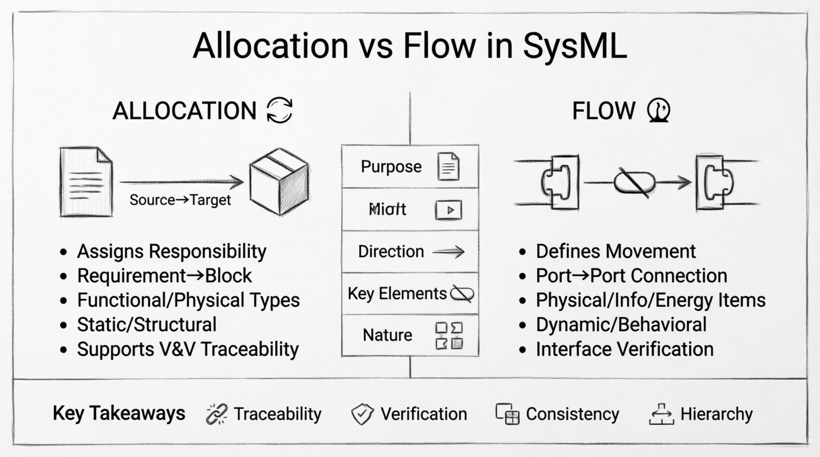
4. Comparative Analysis: Allocation vs. Flow 📊
To ensure clarity, let us compare these two relationship types side-by-side. Understanding the distinction is vital for maintaining model hygiene.
Feature | Allocation Relationship | Flow Relationship |
|---|---|---|
Primary Purpose | Assign responsibility or capability | Define movement or exchange |
Direction | Source (Requirement) → Target (Block) | Source Port → Target Port |
Key Element | Requirement, Activity, Block | Flow Item, Port, Connector |
Verification Link | Directly supports V&V | Supports Interface Verification |
Dynamic Nature | Static (Structure/Responsibility) | Dynamic (Behavior/Interaction) |
Example | “Battery supplies Power” | “Power flows from Battery to Motor” |
5. Implementation Strategies and Best Practices 🛠️
Building a robust model requires discipline. Here are strategies to ensure your Allocation and Flow relationships remain consistent and useful.
5.1. Consistency in Naming
Use clear names for Flow Items. Instead of “Data”, use “Telemetry Data”.
Name Allocation relationships based on the nature of the assignment. Use “Allocates To” for requirements.
Avoid generic labels that do not add semantic value.
5.2. Hierarchy Management
Systems are hierarchical. A top-level system breaks down into subsystems, which break down into components. Relationships should respect this hierarchy.
Upward Allocation: A high-level requirement allocates to a subsystem. The subsystem then allocates to its components. Do not skip levels unless necessary for high-level traceability.
Downward Flow: Flows should traverse from top-level interfaces down to specific implementation ports. Ensure that the flow is decomposed as the architecture decomposes.
5.3. Interface Definition
Flows often cross system boundaries. Define these boundaries clearly using Interface Blocks. An Interface Block defines the contract for a flow without specifying the implementation.
Use Usage Properties to indicate where a block requires an interface.
Use Provided Properties to indicate where a block offers an interface.
Connect flows to these properties to ensure that the model reflects the actual system integration points.
6. Common Pitfalls and How to Avoid Them ⚠️
Even experienced modelers make mistakes. Identifying common errors early can save significant rework later.
6.1. Mixing Allocation and Flow
A frequent error is using a Flow relationship to represent a requirement assignment. Do not use a connector to show that a block satisfies a requirement. Use an Allocation relationship for that. Mixing them confuses the model semantics and breaks automated traceability checks.
6.2. Orphaned Flows
A flow that connects to a port that does not exist is an error. Always ensure that the source and target ports are defined on the respective blocks. If a block is deleted, all flows connected to it must be reviewed or removed.
6.3. Over-Allocating Requirements
Do not allocate a single requirement to multiple components unless it is a shared responsibility. If a requirement is allocated to three blocks, it implies all three must satisfy the requirement independently. This can lead to redundancy. If it is a shared constraint, clarify the nature of the allocation.
6.4. Ignoring Flow Direction
Forces and data have direction. A flow of power from a battery to a motor is different from a flow from a motor to a battery (regenerative braking). Ensure the arrow direction matches the physical reality of the system.
7. Integration with Other SysML Diagrams 📄
These relationships are not confined to the Block Definition Diagram (BDD) or Internal Block Diagram (IBD). They appear across the modeling landscape.
7.1. Requirements Diagram
While primarily used for requirement decomposition, allocation is often visualized here. You can show how a parent requirement allocates to child requirements, and how those allocate to system elements. This creates a direct line of sight from stakeholder needs to technical specifications.
7.2. Sequence Diagram
Sequence diagrams focus on the timing of interactions. Flow relationships provide the context for the messages exchanged. The messages in a Sequence Diagram often represent the Flow Items defined in the IBD. Ensure consistency between the data types in the Sequence Diagram and the Flow Items in the IBD.
7.3. Parametric Diagram
Parametric diagrams define constraints on values. Flows often carry the values that are constrained. For example, a flow carrying “Voltage” might be constrained by a parametric equation in a constraint block. Link the Flow Item to the variable in the constraint block to enable simulation.
8. Traceability and Verification Workflows 🔍
The true power of SysML lies in its ability to trace requirements through the lifecycle. Allocation and Flow are the engines of this traceability.
8.1. Verification Matrices
Using Allocation relationships, you can generate a Verification Matrix. This matrix lists requirements and the corresponding blocks responsible for them. During testing, you can map test cases to these blocks. If a test fails, the matrix tells you exactly which requirement and which component are affected.
8.2. Interface Verification
Flow relationships enable interface verification. You can define test cases that verify the data types and rates of flows. For example, does the “Speed Signal” flow from the sensor to the controller match the expected frequency? Flow relationships define the connection points for these tests.
8.3. Change Impact Analysis
When a requirement changes, the Allocation relationship tells you which blocks are impacted. When an interface changes, the Flow relationship tells you which connected blocks need to be updated. This minimizes the risk of breaking the system during updates.
9. Advanced Considerations for Complex Systems 🚀
As systems grow in complexity, simple allocation and flow may not suffice. You must consider advanced modeling techniques.
9.1. Mappings
Sometimes, a single requirement is satisfied by a combination of blocks. This requires mapping rather than direct allocation. You may need to group blocks under a higher-level allocation to represent a composite capability.
9.2. State-Based Flows
Not all flows are active all the time. Some flows are conditional based on the system state. While SysML does not natively model time-varying flow availability in the IBD, you can use State Machine diagrams to control the activation of flows. Link the State Machine transitions to the Flow connectors to represent conditional connectivity.
9.3. Parameter Propagation
In parametric modeling, flows carry parameters that affect calculations. Ensure that the units and dimensions of Flow Items match the expectations of the receiving ports. Mismatched units can lead to simulation errors or physical design flaws.
10. Maintaining Model Integrity Over Time 📅
A model is a living artifact. It evolves as the system evolves. To keep Allocation and Flow relationships effective:
Regular Reviews: Schedule periodic reviews of the relationship graph. Check for broken links or orphaned elements.
Version Control: Treat the model file as code. Use version control to track changes in relationships.
Documentation: Add comments to complex allocations or flows. Explain the “why” behind the relationship, not just the “what”.
Tooling: Use automated consistency checks provided by modeling tools to flag violations in relationship definitions.
11. Summary of Key Takeaways ✅
Allocation assigns responsibility. It links Requirements to Blocks and Activities to Parts. It is static and structural.
Flow defines interaction. It links Ports via Flow Items. It is dynamic and behavioral.
Traceability depends on clear Allocation. Verification depends on clear Flow.
Consistency is paramount. Do not mix relationship types or ignore directionality.
Hierarchy must be respected. Decompose both responsibilities and flows as you move from system to component.
Mastering these relationships is not about memorizing syntax. It is about understanding the physical and logical realities of the system you are modeling. When done correctly, Allocation and Flow relationships provide a robust framework that supports engineering decisions, risk reduction, and successful system delivery.
By adhering to the principles outlined in this guide, you ensure that your SysML models remain accurate, verifiable, and valuable assets throughout the entire product lifecycle. Focus on clarity, maintain discipline in your relationships, and let the model drive the engineering process.