


Welcome to the world of systems engineering. As you step into your new role, you will encounter a language designed to bridge the gap between requirements, design, and behavior. This language is SysML, the Systems Modeling Language. It is the backbone of modern complex system design, allowing teams to visualize, specify, analyze, and verify systems before a single physical component is built. This guide is structured to help you navigate the core concepts without relying on specific software tools, focusing instead on the underlying principles that apply regardless of the environment you use.
🌐 What is SysML?
SysML is a general-purpose modeling language for systems engineering applications. It is based on the Unified Modeling Language (UML) but has been modified and extended to support the unique needs of systems engineering. While UML focuses heavily on software, SysML addresses the broader spectrum of system elements, including hardware, software, data, personnel, and facilities.
Standardization: It is an Object Management Group (OMG) standard, ensuring consistency across industries.
Visual Representation: It allows complex systems to be represented visually, making it easier to communicate ideas across multidisciplinary teams.
Traceability: It provides a framework to link requirements to design elements, ensuring that every part of the system fulfills a specific need.
Interoperability: Models created in one environment can often be exchanged with others, facilitating collaboration.
For a new hire, understanding SysML is not just about learning symbols; it is about adopting a structured way of thinking about complexity. It forces you to break down large problems into manageable blocks and define how they interact.
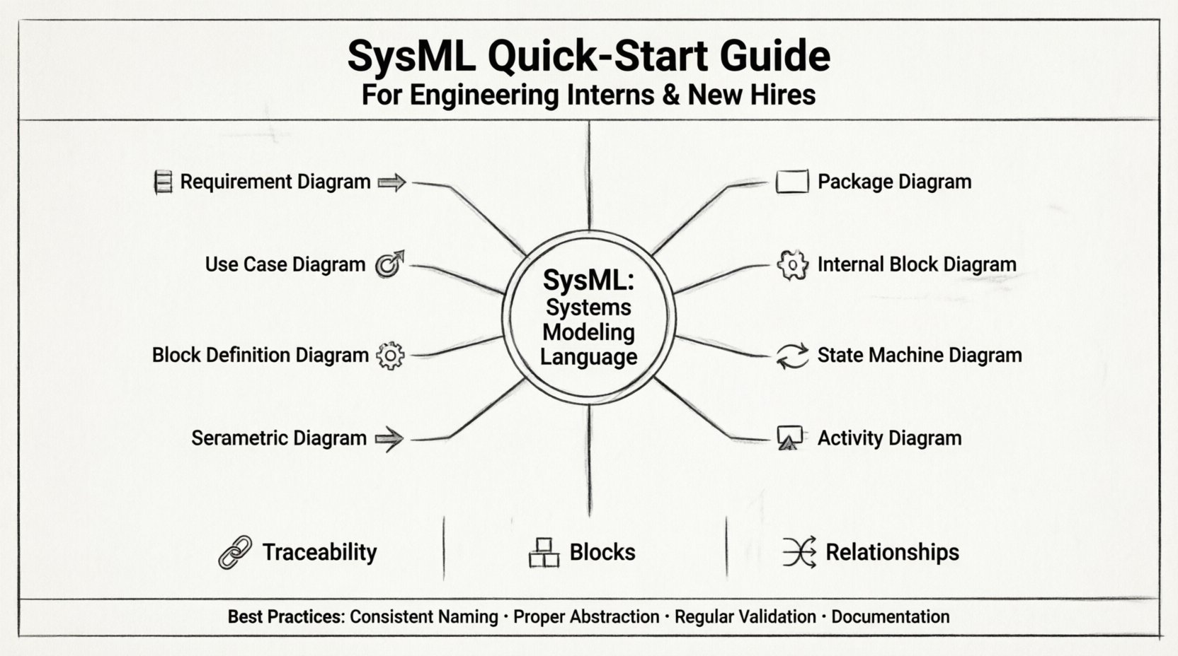
🧩 The Core Diagram Types
SysML defines nine specific diagram types, each serving a distinct purpose within the systems engineering lifecycle. You will likely encounter these repeatedly. Understanding when to use which diagram is a critical skill.
Diagram Type | Primary Focus | Common Use Case |
|---|---|---|
Requirement Diagram 📋 | Stakeholder Needs | Tracking requirements and their satisfaction. |
Use Case Diagram 🎯 | System Functionality | Describing how actors interact with the system. |
Block Definition Diagram 🧱 | System Structure | Defining the static structure and composition. |
Internal Block Diagram ⚙️ | Internal Connections | Showing flows and connections between parts. |
Parametric Diagram 📈 | Mathematical Constraints | Modeling equations and performance constraints. |
Sequence Diagram 📊 | Time-Ordered Behavior | Describing interactions over time between objects. |
State Machine Diagram 🔄 | State Logic | Defining how a system responds to events. |
Activity Diagram 🎬 | Process Flow | Modeling workflows and decision logic. |
Package Diagram 📂 | Organization | Organizing model elements into groups. |
1. Requirement Diagram 📋
This diagram is the anchor of your modeling efforts. It documents what the system must do or be. It is the first place you look when starting a new project. You will define text-based requirements and link them to other elements using relationships.
Traceability: You will link requirements to use cases, blocks, or other requirements.
Relationship Types: Common links include Satisfy (a design element meets a requirement), Derive (one requirement is derived from another), and Refine (providing more detail).
Verification: Later in the lifecycle, you will link these requirements to test cases to ensure they are validated.
2. Use Case Diagram 🎯
Use Case diagrams describe the functional requirements of the system from the perspective of the user or external system. They answer the question: “What can the system do?”
Actors: These represent users, other systems, or external entities that interact with the system.
Use Cases: These represent specific functions or goals the actor wants to achieve.
Relationships: You will use Includes to show that one use case always involves another, and Extends to show optional or conditional behavior.
3. Block Definition Diagram 🧱
This is the structural backbone of your model. It defines the components of the system. In SysML, a Block is the fundamental unit of structure. It can represent a physical part, a software module, or a logical concept.
Composition: You will define how blocks are composed of other blocks. For example, a Vehicle block is composed of Engine, Chassis, and Wheels.
Properties: Blocks have properties (attributes) that define their characteristics, such as mass, voltage, or capacity.
Operations: Blocks can also have operations (behaviors) that they perform.
4. Internal Block Diagram ⚙️
Once you have defined your blocks in the Block Definition Diagram, the Internal Block Diagram (IBD) shows how they connect. It zooms in on the interior of a block to show ports and flows.
Ports: These are the interaction points on a block. They define how a block communicates with its environment.
Flows: These represent the transfer of information, material, or energy between ports.
Interface Blocks: You will often define interface blocks to standardize the connection points between different sub-systems.
5. Parametric Diagram 📈
This diagram is used for performance analysis. It allows you to define mathematical constraints and equations that govern the system’s behavior.
Constraints: You will define equations (e.g., Force = Mass × Acceleration) and link them to block properties.
Validation: This is crucial for verifying that the design meets physical laws or performance specifications before manufacturing.
6. Sequence Diagram 📊
Sequence diagrams capture the time-ordered interactions between objects. They are essential for understanding dynamic behavior.
Lifelines: These represent the objects or actors involved in the interaction.
Messages: These are the signals passed between lifelines, ordered from top to bottom.
Focus of Control: This shows the period during which an object is active.
7. State Machine Diagram 🔄
State machines describe how a system changes its state in response to events. This is vital for systems with complex logic or modes of operation.
States: These represent conditions in which the system exists (e.g., Idle, Running, Error).
Transitions: These are the arrows that move the system from one state to another.
Triggers: Events that cause a transition (e.g., Button Press, Timeout).
Actions: Activities that occur upon entering or exiting a state.
8. Activity Diagram 🎬
Activity diagrams are similar to flowcharts. They model the flow of activities within a system, including decision points and parallel processes.
Swimlanes: These organize activities by the actor or block responsible for them.
Forks and Joins: These allow you to model concurrent behaviors.
Decision Nodes: These represent branching logic based on conditions.
9. Package Diagram 📂
As models grow, they become complex. Package diagrams allow you to organize elements into logical groups. This is essential for managing large systems and distributing work among teams.
Namespaces: Packages provide a namespace to avoid naming conflicts.
Import: You can import elements from one package into another to reuse definitions.
🔗 Relationships and Dependencies
SysML relies heavily on relationships to connect the elements within your diagrams. Understanding these is crucial for a valid model.
Association: A structural link between objects. It represents a static relationship.
Dependency: A usage relationship where one element depends on another. If the supplier changes, the client may need to change.
Generalization: This represents an inheritance relationship, similar to Object-Oriented Programming. A specific type of block is a specialized version of a general block.
Realization: This links an interface to the block that implements it. It is critical for defining contracts between components.
Requirement Relationships: As mentioned earlier, these include Derive, Refine, Satisfy, and Verify. They ensure the model remains aligned with stakeholder needs.
📋 Requirements Management
In systems engineering, requirements are the law. If a design element does not trace back to a requirement, it is considered scope creep or unnecessary complexity. SysML provides a robust framework for managing this.
Requirement Hierarchy: You can nest requirements to create a hierarchy, breaking down high-level system needs into lower-level subsystem needs.
Allocation: This is the process of assigning requirements to specific blocks. It ensures that every requirement has an owner within the design.
Traceability Matrix: A model should always allow you to generate a traceability matrix. This report shows which requirements are satisfied by which design elements and which tests verify them.
✅ Modeling Best Practices
To maintain a healthy model, new engineers should adhere to specific best practices. A model that is not well-structured is difficult to maintain and often becomes obsolete.
1. Naming Conventions
Consistent naming is vital. Avoid generic names like Block1 or Part_A. Instead, use descriptive names like HydraulicPump or ControlUnit. This makes the model readable without needing to open every element.
2. Levels of Abstraction
Do not try to model everything at once. Start at the system level. As you drill down, create separate packages or views for subsystems. This prevents the model from becoming a single, unreadable mess of lines and boxes.
3. Reuse
If you have a standard component (like a sensor or a power supply) that is used across multiple projects, model it once and reuse it. This saves time and ensures consistency.
4. Documentation
Every block and requirement should have a text description. The diagram is a visual aid, but the text provides the context. Do not rely solely on the visual representation.
5. Regular Validation
Run validation checks within your modeling environment regularly. These checks can identify orphaned elements, naming conflicts, or broken relationships.
⚠️ Common Pitfalls to Avoid
Even experienced engineers make mistakes. Being aware of common pitfalls can save you significant time during code reviews and model audits.
Over-Modeling: Creating a model that is too detailed for the current phase of the project. Keep the level of detail appropriate for the design stage.
Ignoring Interfaces: Focusing only on the internal behavior of a block and ignoring how it connects to the outside world. Interfaces are where integration errors occur.
Disconnected Diagrams: Creating diagrams that do not link to the requirements. If a diagram has no traceability, it is just a drawing, not a model.
Hard-Coding: Avoid defining fixed values in the model that should be parameters. Use variables so that the model can be analyzed under different conditions.
Lack of Version Control: Treat your model like code. Use version control systems to track changes. Do not overwrite files without a log.
🚀 Moving Forward
Mastering SysML is a journey that continues throughout your career. It is not a skill you acquire in a week. As you gain experience, you will find that the language evolves to meet your specific domain needs.
Start by focusing on the core diagrams: Requirement, Block Definition, and Internal Block. These three will cover the majority of your daily tasks. Once you are comfortable with structure and requirements, expand into behavior (Activity, State Machine, Sequence) and performance (Parametric).
Remember that the goal of modeling is communication. If your model cannot be understood by your peers or stakeholders, it has not served its purpose. Prioritize clarity over complexity. A simple, accurate model is far more valuable than a complex, ambiguous one.
Engage with your team. Ask questions about why certain modeling decisions were made. Participate in reviews. The community of practice around systems engineering is vast and supportive. There are many resources available online and through industry organizations to deepen your understanding.
Finally, keep your model up to date. A model that does not reflect the current design is worse than no model at all, as it can lead to errors in manufacturing and testing. Treat the model as a living document that evolves with the product.
📚 Summary of Key Concepts
SysML is the standard language for systems engineering modeling.
9 Diagram Types cover structure, behavior, and requirements.
Requirements are the foundation; everything traces back to them.
Blocks represent the physical and logical components.
Relationships link elements together to form a coherent whole.
Traceability ensures that design satisfies stakeholder needs.
Best Practices include consistent naming, proper abstraction, and regular validation.
By internalizing these concepts and applying them consistently, you will contribute effectively to your engineering team. You will help reduce risk, improve communication, and accelerate the development of complex systems. Welcome to the team, and good luck with your modeling journey.