


Systems engineering projects often face a significant hurdle: communication. Engineers focus on logic, interfaces, and constraints. Stakeholders focus on value, cost, and user outcomes. When these two groups operate in silos, the final product often misses the mark. Systems Modeling Language (SysML) offers a standardized approach to bridge this divide. It provides a visual and textual framework that allows both technical teams and business leaders to discuss system goals with clarity and precision. This guide explores how to leverage SysML to ensure every stakeholder understands the system’s intent and how engineers execute it.
📉 The Communication Gap in Systems Engineering
Modern systems are intricate. They combine software, hardware, and human processes. Traditional documentation methods, such as Word documents or spreadsheets, often fail to capture the dynamic relationships between these components. Ambiguity is the enemy of alignment. A phrase like “high reliability” means different things to a finance director and a lead engineer. Without a common language, assumptions fill the void, leading to rework and budget overruns.
Alignment is not just about agreement; it is about shared understanding. When stakeholders and engineers look at a model, they should see the same truth. SysML facilitates this by separating the concerns of different roles while maintaining traceability. It allows the business to define what the system must do, while the engineering team defines how the system will do it. The language itself acts as the contract.
📊 What SysML Brings to the Table
Systems Modeling Language is a general-purpose modeling language for systems engineering applications. It is based on the Unified Modeling Language (UML) but extends it with specific constructs for systems engineering. Unlike proprietary tools that lock users into specific workflows, SysML is an open standard. This openness ensures that the models represent the system logic, not the software syntax.
Key benefits include:
Standardization: A universal notation understood across industries.
Visualization: Complex logic translated into readable diagrams.
Traceability: Links between requirements, design, and verification.
Consistency: Automated checks prevent contradictory specifications.
🧩 Key Diagrams for Alignment
To achieve alignment, you do not need every diagram in the SysML suite. You need the right ones to communicate specific aspects of the system. The following diagrams are most effective for bridging the gap between business needs and technical implementation.
1. Requirements Diagrams (REQ)
This diagram is the foundation of alignment. It captures stakeholder needs and refines them into formal requirements. It allows stakeholders to see their input reflected in the project documentation. You can group requirements by hierarchy, priority, or source.
Use Case: Show where requirements come from (e.g., Safety, Performance).
Allocation: Link requirements to specific system components.
2. Use Case Diagrams (UC)
Use Case diagrams describe the functional behavior of the system from the perspective of the user. They are excellent for engaging non-technical stakeholders because they focus on interactions rather than internal logic.
Actors: Define who interacts with the system (e.g., Pilot, Maintenance Crew).
Use Cases: Define what the system does (e.g., Initiate Launch, Monitor Status).
3. Block Definition Diagrams (BDD)
Block Definition Diagrams represent the static structure of the system. They show the composition of the system and the interfaces between parts. This is where engineers and stakeholders agree on the physical or logical boundaries.
Blocks: Represent system components.
Relationships: Show aggregation, generalization, and dependencies.
4. Internal Block Diagrams (IBD)
While BDD shows the parts, IBD shows how those parts connect. It details the flow of data, energy, and material. This is critical for ensuring that the interface definitions match the actual implementation plans.
Ports: Define interaction points.
Flows: Define the data or signals moving between blocks.
🗺️ Mapping Needs to Models
Understanding which diagram serves which purpose is vital for effective collaboration. The table below outlines how different stakeholder views translate into SysML elements.
Stakeholder View | SysML Element | Benefit |
|---|---|---|
Business Value | Requirement | Clear goals and measurable outcomes |
User Interaction | Use Case | Functional clarity without technical jargon |
Technical Structure | Block Definition | Architecture visibility and component breakdown |
Interface Control | Internal Block Diagram | Physical and logical connectivity definition |
Performance Constraints | Parametric Diagram | Mathematical verification of constraints |
🔗 Traceability: Connecting the Dots
Traceability is the backbone of alignment. It ensures that every decision can be traced back to a stakeholder need, and every requirement is verified by a test. Without traceability, changes in one area can inadvertently break another. SysML supports this through explicit relationships.
Key traceability relationships include:
Refine: Breaking down high-level needs into detailed requirements.
Satisfy: Linking a design element to the requirement it fulfills.
Verify: Linking a test case to the requirement it validates.
Derive: Showing how one requirement was derived from another.
When stakeholders review the model, they can follow these links. If a requirement changes, the impact analysis is immediate. The model highlights which blocks, use cases, or tests are affected. This transparency builds trust.
🚀 Practical Workflow for Collaboration
Implementing SysML requires a structured approach. It is not a tool to be applied after the fact; it is a process to be followed from the start.
Step 1: Elicitation and Capture
Begin by gathering input from all relevant stakeholders. Do not rely on a single source. Use workshops to define the initial scope. Capture these inputs as high-level requirements in the Requirements Diagram. Ensure the language is unambiguous.
Step 2: Functional Decomposition
Break down the system into functional blocks. Use Use Case Diagrams to ensure all functions are accounted for. Involve the stakeholders in this step to confirm that the functions align with their expectations of the user experience.
Step 3: Structural Definition
Define the physical or logical components. Use Block Definition Diagrams to outline the system architecture. Discuss interfaces here. This is often where the most technical disagreements occur, so keep the dialogue open and focused on data flow.
Step 4: Verification and Validation
Once the model is established, verify that it meets the requirements. Validate that the system solves the original problem. Use Parametric Diagrams for quantitative checks, such as mass, power, or timing constraints.
⚠️ Common Challenges & Solutions
Adopting a modeling language involves obstacles. Recognizing these early helps in mitigating risks.
Model Drift: Over time, the model may diverge from the actual system. Solution: Integrate model updates into the standard change management process. Do not treat the model as a separate artifact.
Complexity: Models can become too detailed too quickly. Solution: Adopt a top-down approach. Start with high-level blocks and refine only when necessary.
Resistance: Stakeholders may find diagrams abstract. Solution: Use annotations and comments to explain technical terms. Keep the views tailored to the audience.
Maintenance: Keeping the model current requires effort. Solution: Assign ownership of specific model sections to specific team members.
✅ Best Practices for Modeling
To maintain high alignment and low friction, adhere to these principles:
Keep It Simple: Avoid over-engineering the model. Use the simplest notation that conveys the necessary information.
Update Regularly: Treat the model as a living document. Schedule reviews at key milestones.
Involve Stakeholders Early: Do not wait for the final design to show them the model. Show them the requirements and use cases first.
Define Naming Conventions: Ensure consistency in how blocks and requirements are named to avoid confusion.
Focus on Interfaces: Spend the most effort defining interfaces. This is where integration failures usually happen.
🔄 Maintaining Alignment Over Time
Alignment is not a one-time event. It is a continuous process. As the project evolves, requirements change, and new risks emerge. The model must evolve with them. This requires discipline.
When a requirement changes, the model should trigger a review. Ask these questions:
Does this change impact the system architecture?
Are there any downstream effects on verification activities?
Have all stakeholders been notified of the change?
By maintaining a rigorous link between the model and the project status, you ensure that the system goals remain the North Star throughout the development lifecycle. The model becomes the single source of truth, reducing the need for repetitive meetings to clarify intent.
📈 Measuring Success
How do you know if SysML has successfully aligned your team? Look for specific indicators:
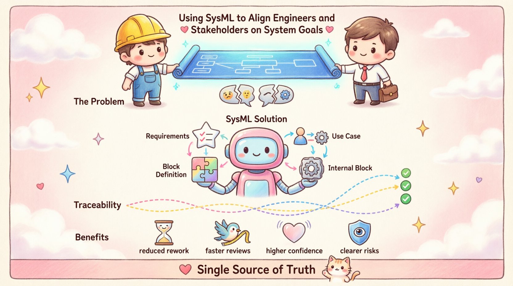
Reduced Rework: Fewer design changes required after implementation begins.
Faster Reviews: Stakeholder reviews take less time because the information is clear.
Higher Confidence: Technical teams feel more confident that they understand the business needs.
Clearer Risks: Risks are identified earlier in the lifecycle.
These metrics indicate that the communication channels are open and the shared understanding is strong. The focus shifts from debating the meaning of the requirements to solving the problems defined by them.
🤝 The Human Element
Technology alone does not create alignment. The people using the tools matter. Training is essential. Engineers need to understand the business context, and stakeholders need to understand the technical constraints. SysML supports this by forcing a discussion about the system boundaries.
When a stakeholder asks about a requirement, the engineer can point to the model. When an engineer proposes a design change, the stakeholder can see the impact on the requirements. This visual evidence removes emotion from the decision-making process. It grounds the conversation in facts.
Encourage a culture where the model is the reference point. If it is not in the model, it is not in the system. This rule simplifies scope creep management. It forces discipline on adding features that do not support the system goals.
🛡️ Security and Compliance
In regulated industries, traceability is often a legal requirement. SysML provides the structure needed to demonstrate compliance. You can show auditors exactly how a safety requirement was traced to a design element and verified by a test. This documentation is invaluable during certification processes.
By embedding compliance requirements into the model from the start, you avoid the last-minute scramble to generate evidence. The model serves as the audit trail. This proactive approach saves time and reduces the risk of non-compliance penalties.
🌟 Summary of Benefits
Using SysML to align engineers and stakeholders is about more than drawing diagrams. It is about establishing a rigorous framework for collaboration. It transforms vague aspirations into concrete specifications. It turns abstract needs into verifiable designs. The result is a system that works as intended, delivered on time and within budget.
The path to alignment is clear. Define the goals, model the structure, trace the logic, and validate the outcomes. By following this disciplined approach, organizations can reduce friction and increase the quality of their engineering output. The system becomes a shared vision, realized through coordinated effort.