


In complex engineering environments, the gap between abstract requirements and physical implementation often leads to costly misunderstandings. A shared language is essential for stakeholders to visualize, analyze, and validate system behavior before construction begins. Systems Modeling Language (SysML) provides a standardized framework for this purpose. By utilizing precise notation, teams can ensure that architectural decisions are documented, traceable, and unambiguous. This guide explores how to leverage SysML to communicate system architecture effectively.
Why Standardized Modeling Matters 🤝
Engineering projects frequently involve diverse groups of people: requirements engineers, system architects, software developers, and hardware specialists. Verbal descriptions or static documents often fail to capture the dynamic interactions between system components. Diagrams serve as the bridge, but only if they follow a consistent standard. Without a unified notation, interpretations vary, leading to integration failures.
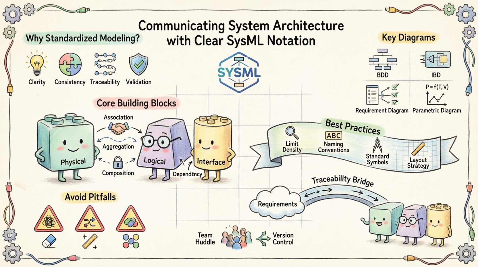
- Clarity: Visual models reduce cognitive load compared to dense text specifications.
- Consistency: Standard symbols ensure that a block means the same thing to everyone.
- Traceability: Linking requirements to structural elements ensures nothing is overlooked.
- Validation: Models allow for simulation and analysis early in the lifecycle.
When architecture is communicated clearly, the risk of rework decreases significantly. Teams spend less time clarifying intent and more time implementing solutions. This efficiency is critical in industries where safety and reliability are paramount, such as aerospace, automotive, and medical devices.
Understanding the Core Building Blocks 🧱
Before constructing complex diagrams, it is necessary to understand the fundamental elements that make up a SysML model. These elements form the vocabulary of the notation. Mastery of these primitives allows for the creation of meaningful architecture descriptions.
The Block: The Primary Unit of Structure
The Block is the most fundamental construct in SysML. It represents a physical or logical part of the system. A block encapsulates structure, behavior, and requirements. When defining an architecture, every component, subsystem, or interface is modeled as a block.
- Physical Blocks: Represent hardware components like sensors, actuators, or processors.
- Logical Blocks: Represent software modules, functions, or data structures.
- Interface Blocks: Define the contract for interaction between components.
Attributes define the properties of a block, such as mass, voltage, or data type. Operations define the actions a block can perform. This separation allows architects to focus on what a component does without getting bogged down in internal implementation details immediately.
Relationships and Connections
Blocks do not exist in isolation. Relationships define how blocks interact. The type of relationship chosen dictates the nature of the connection.
- Association: A structural link indicating that instances of one block can be linked to instances of another. Used for physical connections or logical dependencies.
- Aggregation: A whole-part relationship where parts can exist independently of the whole. Useful for assemblies.
- Composition: A strong whole-part relationship where parts cannot exist without the whole. Used for tightly coupled subsystems.
- Dependency: A usage relationship where one block relies on another to function.
Key Diagrams for Architecture Communication 📝
SysML offers nine specific diagram types. Not all are needed for every project. For communicating system architecture, a subset of diagrams provides the most value. Selecting the right view for the right audience is a skill in itself.
1. Block Definition Diagram (BDD) 📊
The Block Definition Diagram is the backbone of system architecture. It defines the structure of the system and the relationships between its parts. This diagram answers the question: “What is the system made of?”
When creating a BDD, focus on hierarchy. Start with the top-level system and decompose it into major subsystems. Use composition and aggregation to show containment. Use associations to show interaction between sibling or peer subsystems.
- Scope: Keep the diagram focused on structure. Avoid cluttering it with flow details.
- Levels: Use separate BDDs for different levels of abstraction (System, Subsystem, Component).
- Interfaces: Clearly mark ports and interfaces to show where external connections occur.
2. Internal Block Diagram (IBD) ⚙️
While the BDD defines what exists, the Internal Block Diagram defines how it connects. It is a detailed view of a specific block, showing its internal composition. This diagram answers: “How do the parts inside this system talk to each other?”
IBDs are crucial for showing data flow, signal flow, and physical connections. They allow architects to drill down from a high-level block into its internal wiring.
- Parts: Show the blocks contained within the parent block.
- Ports: Define the access points for interaction.
- Connectors: Draw lines between ports to indicate the flow of information or material.
3. Requirement Diagram 📋
Architecture must serve a purpose. The Requirement Diagram links the structural model to the constraints and needs of the project. It ensures that every block in the architecture has a justification.
Requirements are modeled as separate elements that can be allocated to blocks. This creates a traceability matrix within the model. If a requirement changes, the impact on the architecture is immediately visible.
- Allocation: Link requirements to the blocks that satisfy them.
- Verification: Define how the requirement will be tested or verified.
- Refinement: Break down high-level requirements into detailed specifications.
4. Parametric Diagram 📈
For systems where performance is critical, the Parametric Diagram provides mathematical rigor. It defines constraints and equations that govern the system’s behavior. This is essential for verifying that the architecture meets performance goals.
Constraints are modeled as equations or relationships between variables. Solving these equations allows engineers to check if the design is viable under specific conditions.
- Variables: Define inputs, outputs, and intermediate values.
- Constraints: Apply mathematical rules to variables.
- Solver: Use the model to calculate values and check feasibility.
Best Practices for Readability and Clarity ✨
Even with the correct diagram types, a model can become unreadable if not managed well. A cluttered diagram confuses stakeholders rather than informing them. Adhering to specific design principles ensures the model remains a useful communication tool.
1. Limit Information Density
Do not attempt to show the entire system on a single page. Overcrowding diagrams makes them impossible to follow. Instead, use decomposition.
- Break complex subsystems into their own diagrams.
- Use reference blocks to simplify high-level views.
- Keep labels concise and descriptive.
2. Consistent Naming Conventions
Naming conventions are the grammar of your model. If one engineer names a block “Sensor_A” and another names it “Temp_Sensor”, confusion arises. Establish a naming standard at the start of the project.
- Use nouns for blocks and verbs for operations.
- Include version or revision numbers if necessary.
- Ensure names are unique across the model.
3. Use Standard Notation Symbols
Deviation from the standard notation creates ambiguity. If you draw a custom symbol for an interface, other engineers will not know its meaning. Always use the standard SysML shapes for blocks, ports, and connectors.
| Element | Standard Symbol | Purpose |
|---|---|---|
| Block | Rectangle with name box | Represents a component or subsystem |
| Port | Small rectangle on edge | Represents an interaction point |
| Connector | Solid line | Represents a structural link |
| Requirement | Rectangle with dashed border | Represents a need or constraint |
| Constraint | Ellipse | Represents a mathematical rule |
4. Color and Layout Strategy
While avoiding CSS styles, the logical layout of elements matters. Group related components together. Use white space effectively to separate distinct functional areas. If the modeling tool allows, use color coding to indicate status or ownership, but ensure it is accessible and meaningful.
Bridging Requirements and Structure 🔗
One of the most common failures in systems engineering is the disconnect between what is required and what is built. SysML addresses this through explicit allocation. This process ensures that the architecture is not just a drawing, but a functional specification.
Traceability Chains
A traceability chain links a high-level stakeholder requirement down to specific system components. This chain allows impact analysis. If a requirement changes, you can trace it to the specific block that needs modification.
- Upward Traceability: Ensure every block serves a requirement.
- Downward Traceability: Ensure every requirement is satisfied by a block.
- Bidirectional: Allow navigation between the requirement and the implementation.
Validation and Verification
Models support V&V (Verification and Validation). Verification asks, “Did we build the system right?” Validation asks, “Did we build the right system?”
By linking requirements to the model, you can simulate the system to verify performance. You can also review the model to validate that it meets the stakeholder needs. This reduces the risk of discovering issues during physical testing.
Common Pitfalls and How to Avoid Them ⚠️
Even experienced engineers make mistakes when modeling architecture. Recognizing common pitfalls helps teams maintain model quality over time.
1. The “Big Model” Syndrome
Teams often try to create one massive model containing every detail. This becomes unmanageable and slow. It is better to use a modular approach. Create separate models for different domains (Mechanical, Electrical, Software) and link them through interfaces.
2. Over-Modeling
Not every aspect of a system needs to be modeled. Modeling every wire in a harness is unnecessary for high-level architecture. Focus on the critical paths and interfaces. Abstract away the details that do not impact the current decision-making process.
3. Ignoring the Lifecycle
Models should evolve with the project. A static model becomes obsolete quickly. Establish a process for updating the model as the design changes. Regular reviews ensure the model remains accurate.
4. Lack of Governance
Without a review process, model quality degrades. Implement a governance structure where senior engineers review diagrams before they are baselined. This ensures compliance with the standards and conventions established earlier.
Collaboration Strategies for Model-Based Systems 🧩
Architecture is a team effort. The model is the shared artifact that facilitates this collaboration. However, collaboration requires discipline.
1. Role-Based Access
Different team members need to see different parts of the model. Define roles that restrict access to specific diagrams or blocks. This prevents accidental changes and reduces cognitive load for individual contributors.
2. Change Management
Changes in architecture must be managed formally. When a block is modified, notify all stakeholders who depend on it. The model should support versioning to track history and allow rollbacks if necessary.
3. Communication Channels
The model is not the only communication channel. Use it as a reference during meetings. Export views to PDF or image formats for presentations. Ensure that the exported views are labeled and consistent with the live model.
Final Thoughts on Architectural Clarity 🌟
Effective communication of system architecture is not about drawing pretty pictures. It is about creating a precise, logical representation of the system that supports decision-making. SysML provides the tools to build this representation.
By focusing on core building blocks, selecting the appropriate diagrams, and adhering to best practices, teams can reduce ambiguity and improve project outcomes. The investment in modeling pays dividends in reduced rework and clearer understanding across the organization.
Remember that the model is a living document. It requires maintenance, governance, and active use. When treated as a central source of truth, SysML becomes a powerful asset for any systems engineering effort. The goal is not just to document the system, but to understand it deeply before it is built.
As technology evolves, the need for clear architecture communication will only grow. Digital twins, automated testing, and integrated development environments rely on accurate models. Mastering the notation is a step toward future-proofing engineering processes. Start with the basics, build consistency, and let the model guide the development.