


Systems Modeling Language (SysML) is a powerful tool for defining, analyzing, designing, and verifying complex systems. It extends the Unified Modeling Language (UML) specifically for systems engineering tasks. However, the transition from traditional engineering documentation to graphical modeling can be jarring. Many practitioners stumble over common mistakes that lead to models that are difficult to maintain, understand, or validate. This guide outlines the critical pitfalls encountered by novices and provides actionable strategies to navigate them effectively. 🚀
Building a robust model requires discipline. It is not merely about drawing boxes and lines; it is about capturing the logic, constraints, and relationships that govern a system. Below, we explore the most frequent errors and how to correct your approach.
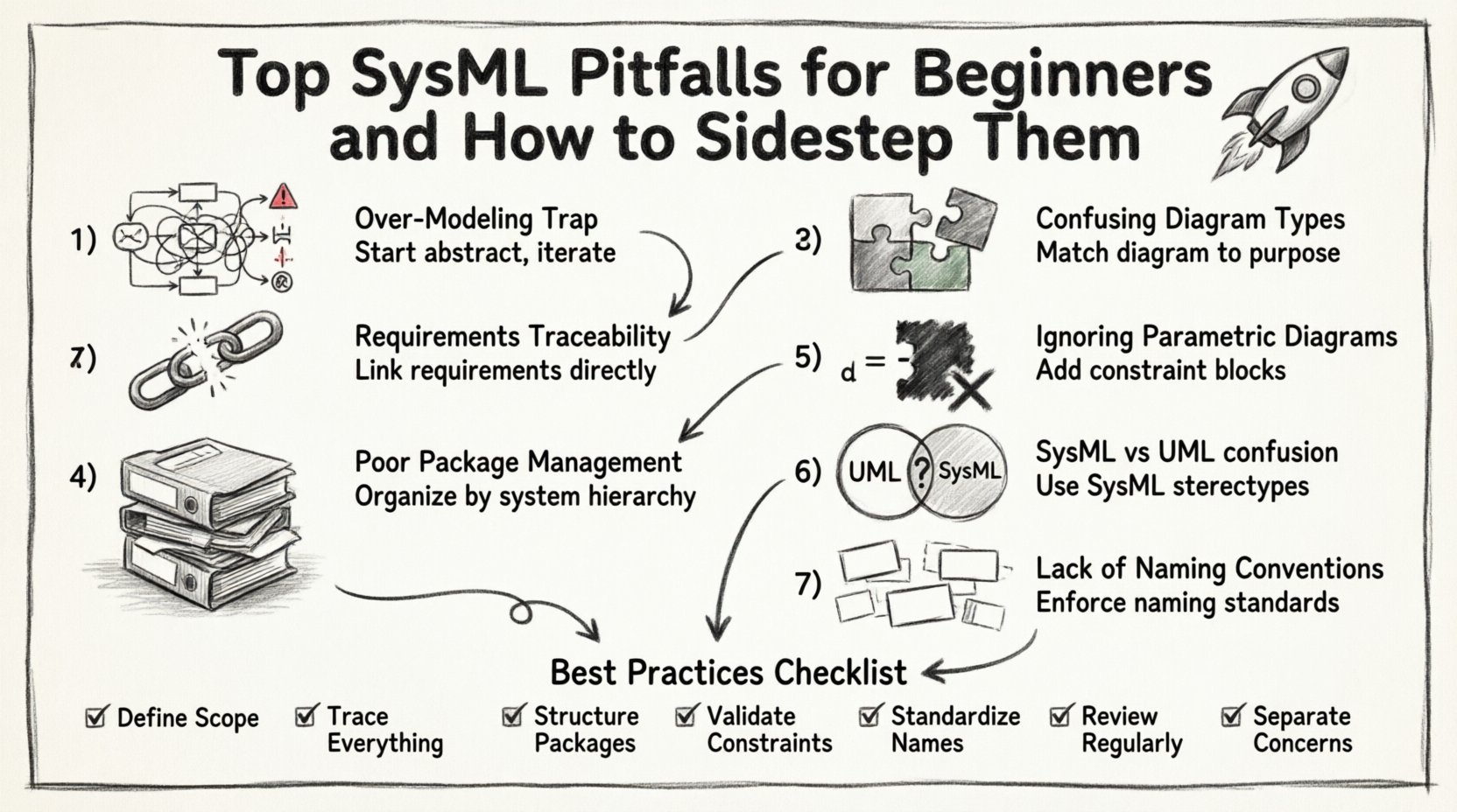
1. The Over-Modeling Trap 📉
One of the most prevalent issues is the tendency to model too much, too soon. Beginners often feel compelled to represent every single detail of the system within the initial model. They aim for perfection in the first draft, resulting in massive, unwieldy diagrams that obscure the core architecture.
Why It Happens
- Perfectionism: The belief that a model must be complete before it is useful.
- Lack of Iteration: Failing to adopt a “top-down” or “bottom-up” iterative approach.
- Confusion: Not knowing which details are necessary for the current phase of the project.
The Consequence
When a model becomes too dense, it loses its primary purpose: communication. Stakeholders cannot find the information they need. Changes become painful because a modification in one obscure corner might break a relationship in another part of the diagram. Maintenance costs skyrocket.
The Solution
- Focus on Abstraction: Start with high-level requirements and block definitions. Drill down into detail only when necessary.
- Iterative Refinement: Build the model in stages. Validate the structure before adding detailed attributes.
- Modularity: Split complex systems into sub-systems. Use packages to isolate specific functionalities.
2. Neglecting Requirements Traceability 📋
Systems engineering relies heavily on the ability to trace a requirement from its origin through to its implementation and verification. Beginners often treat requirements as separate documents, failing to link them directly to model elements. This creates a “black box” scenario where the connection between what is needed and what is built is lost.
Why It Happens
- Separation of Concerns: Keeping requirements in a spreadsheet or Word document.
- Tool Limitations: Using tools that do not support direct linking (though the principle applies regardless of software).
- Effort Perception: Viewing linking as administrative overhead rather than engineering value.
The Consequence
Without traceability, validation becomes a guessing game. If a requirement changes, you do not know which parts of the model are affected. Conversely, if a model element is modified, you cannot easily determine if it still satisfies the original requirement. This breaks the verification and validation (V&V) loop.
The Solution
- Direct Links: Use the dedicated Requirement diagram or link requirements to blocks, cases, or use cases directly.
- Verification Relations: Explicitly define verify, satisfy, and refine relationships.
- Consistency Checks: Regularly run checks to ensure all requirements are linked to at least one model element.
3. Confusing Diagram Types 🧩
SysML provides nine distinct diagram types. Beginners frequently misuse them, leading to confusion about the system’s behavior versus its structure. A common error is using an Activity diagram to show structural composition, or a Sequence diagram to define static requirements.
Understanding the specific use case for each diagram type is crucial for clarity.
| Diagram Type | Primary Purpose | Common Beginner Error |
|---|---|---|
| Block Definition Diagram (BDD) | Define structure, parts, and flows. | Using it for behavior instead of structure. |
| Internal Block Diagram (IBD) | Define connections between parts. | Neglecting interfaces and ports. |
| Use Case Diagram | Define functional requirements. | Overloading with technical details. |
| Activity Diagram | Define behavior and logic flow. | Confusing it with a flowchart of data only. |
| Sequence Diagram | Define interaction over time. | Missing lifelines or interaction fragments. |
| Parametric Diagram | Define constraints and equations. | Ignoring mathematical constraints entirely. |
The Solution
- Define a Standard: Establish a modeling standard that dictates which diagram type to use for specific tasks.
- Review Diagrams: Before adding a diagram, ask: “What am I trying to communicate?”
- Stick to the Standard: Resist the urge to force a structure into a behavior diagram just because it looks familiar.
4. Poor Package Management 📦
As models grow, the hierarchy becomes critical. Beginners often dump all elements into the root package. This leads to a “spaghetti model” where finding an element requires scrolling through hundreds of items. It also makes it difficult to manage dependencies between sub-systems.
Why It Happens
- Speed Over Structure: Creating elements quickly without organizing them.
- Flat Hierarchy: Lack of understanding of namespaces and scoping.
- Fear of Complexity: Avoiding the creation of nested packages.
The Consequence
Collaboration becomes difficult. Two engineers might create elements with the same name in different packages, causing reference errors. Navigating the model to find specific logic becomes a time-consuming task. Version control and merging models also become problematic.
The Solution
- System Decomposition: Organize packages based on the system decomposition hierarchy (e.g., System, Subsystem, Component).
- Importing vs. Copying: Use imports to reference elements rather than duplicating them.
- Regular Housekeeping: Schedule time to review and reorganize packages as the model evolves.
5. Ignoring Parametric Diagrams ⚖️
Parametric diagrams are unique to SysML and allow for the modeling of mathematical constraints and physical properties. Beginners often skip these diagrams entirely, viewing them as optional or too mathematical. They rely solely on block properties for constraints.
Why It Happens
- Lack of Math Background: Engineers may feel uncomfortable with equations.
- Tool Complexity: Setting up constraint blocks can seem intimidating.
- Perceived Irrelevance: Belief that simple properties are sufficient.
The Consequence
The model remains descriptive rather than analytical. You cannot simulate performance, verify mass budgets, or check thermal constraints within the model. The model fails to capture the physical reality of the system, limiting its utility in the design phase.
The Solution
- Start Simple: Begin with a single constraint block for a critical parameter.
- Learn Constraint Blocks: Understand how to define variables and equations within the constraint block.
- Link to Properties: Connect constraint variables to actual block properties to enable validation.
6. Treating SysML as Pure UML 🔄
UML is designed for software engineering, while SysML is designed for systems engineering. A common mistake is applying UML stereotypes and patterns blindly without adapting them to the broader systems context. SysML introduces concepts like requirements and parametric diagrams that do not exist in standard UML.
Why It Happens
- Software Background: Engineers transitioning from software often default to UML habits.
- Tool Defaults: Some modeling environments default to UML profiles.
- Terminology Confusion: Assuming “Class” in UML is the same as “Block” in SysML.
The Consequence
The model lacks the necessary abstractions for hardware, software, and human interactions. You might model a class hierarchy that implies software inheritance when the system actually requires composition or aggregation of physical parts. The semantics of the model become ambiguous.
The Solution
- Study SysML Profiles: Understand the specific extensions SysML adds to UML.
- Use SysML Stereotypes: Ensure you are using SysML-specific stereotypes for blocks, flows, and requirements.
- Focus on System Context: Remember that SysML models systems, not just software components.
7. Lack of Naming Conventions 🏷️
Names in a model are the primary way to identify elements. Beginners often use generic names like “Block1”, “PartA”, or “Flow1”. While this might work for a prototype, it creates confusion in a large-scale project where dozens of engineers are working on the same model.
Why It Happens
- Speed: Typing generic names is faster.
- Lack of Guidelines: No established naming standard exists in the team.
- Refactoring Later: Planning to rename everything after the model is “done” (which never happens).
The Consequence
Readability plummets. New team members cannot understand the model without external documentation. Automated checks and reporting become difficult if element names are inconsistent. The model becomes a liability rather than an asset.
The Solution
- Establish a Standard: Define rules for naming blocks, flows, and requirements (e.g., prefixing with subsystem names).
- Use Comments: Add detailed comments for complex elements, but keep names descriptive.
- Enforce Consistency: Make naming conventions part of the code/model review process.
Best Practices Checklist ✅
To ensure your SysML modeling efforts are effective and sustainable, use the following checklist as a baseline for your workflow.
- Define Scope: Clearly state what the model covers and what it excludes.
- Trace Everything: Ensure every requirement is linked to a model element.
- Structure Packages: Organize elements logically using a hierarchy that mirrors the system decomposition.
- Validate Constraints: Use parametric diagrams to define physical and performance constraints.
- Standardize Names: Adhere to a strict naming convention for all elements.
- Review Regularly: Schedule periodic reviews to remove dead elements and update outdated relationships.
- Separate Concerns: Keep structural, behavioral, and requirements diagrams distinct but linked.
Building a Sustainable Model 🏗️
Creating a SysML model is an exercise in clarity and precision. It requires resisting the urge to rush and the temptation to overcomplicate. By avoiding the pitfalls outlined above, you ensure that the model serves its purpose: to act as a single source of truth for the system design.
Remember that the model is a living artifact. It will change as the system evolves. The discipline you apply now in avoiding common errors will pay dividends in maintenance and communication later. Focus on traceability, modularity, and clear semantics. Treat the diagramming tools as enablers of thought, not just drawing tools.
When you approach SysML with these principles, the complexity of the system becomes manageable. You gain the ability to analyze trade-offs, verify requirements, and communicate design decisions effectively to all stakeholders. The goal is not a perfect model on day one, but a robust framework that supports the engineering lifecycle.
Stay disciplined. Follow the standards. Keep the model simple enough to understand but detailed enough to be useful. This balance is the key to successful systems engineering modeling.