


Systems Engineering is a discipline that focuses on designing, integrating, and managing complex systems over their life cycles. As these systems grow in complexity, traditional documentation methods often struggle to keep pace. This is where the Systems Modeling Language, known as SysML, enters the picture. It provides a standardized visual language to represent system requirements, behavior, structure, and constraints. This guide provides a deep dive into the fundamentals, helping you understand the core mechanics without relying on specific software tools.
What is SysML? 📐
SysML is an open standard general-purpose modeling language. It was developed specifically to address the needs of systems engineering, distinguishing it from the Unified Modeling Language (UML), which was originally designed for software engineering. SysML is a profile of UML, meaning it reuses much of UML’s syntax but specializes the semantics for systems.
When engineers adopt SysML, they move towards Model-Based Systems Engineering (MBSE). This approach shifts the focus from documents to models. A model is a representation of reality that can be analyzed, simulated, and validated. SysML allows stakeholders to communicate complex ideas through diagrams that are universally understood by the industry.
Standardization: Managed by the Object Management Group (OMG).
Interoperability: Models can be exchanged between different environments using XML.
Traceability: Links requirements directly to design elements.
Why Choose SysML Over Other Methods? 🤔
Historically, systems were described using text-heavy specifications. While text is necessary for legal and detailed descriptions, it is often ambiguous. Diagrams offer visual clarity. However, UML is often too software-centric. SysML fills the gap between hardware, software, and human interaction.
Key advantages include:
Hardware Agnostic: SysML models physical components, not just code.
Scalability: The same language applies to a small subsystem or a massive aerospace project.
Early Validation: You can check for consistency and conflicts before building physical prototypes.
Cost Reduction: Identifying errors in the modeling phase is significantly cheaper than fixing them in production.
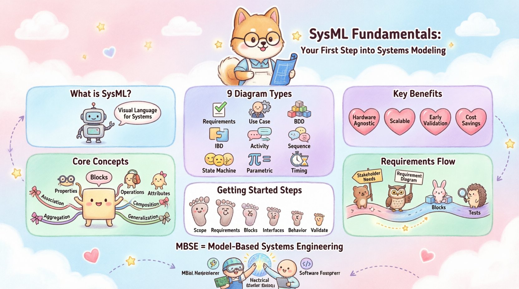
The Nine SysML Diagrams Explained 📊
SysML is built upon nine specific diagram types. Each serves a unique purpose in describing different aspects of the system. Understanding when to use which diagram is crucial for effective modeling.
Diagram Type | Primary Focus | Key Use Case |
|---|---|---|
Requirement Diagram | Requirements | Defining what the system must do. |
Use Case Diagram | Functionality | Describing user interactions and goals. |
Block Definition Diagram (BDD) | Structure | Defining system parts and their relationships. |
Internal Block Diagram (IBD) | Structure | Showing internal flows and connections. |
Activity Diagram | Behavior | Describing the flow of actions or data. |
Sequence Diagram | Behavior | Showing time-ordered interactions between blocks. |
State Machine Diagram | Behavior | Describing states and transitions of a block. |
Parametric Diagram | Constraints | Modeling mathematical and physical constraints. |
Timing Diagram | Behavior | Describing changes in state or values over time. |
Requirement Diagram: This is often the starting point. It captures the needs of the stakeholders. You can link requirements to other elements to ensure every requirement is addressed by the design.
Block Definition Diagram (BDD): This is the structural backbone. It defines the “types” of things in your system. It shows how parts are related to wholes through aggregation or composition. It does not show specific instances, but rather the blueprint.
Internal Block Diagram (IBD): While BDD shows types, IBD shows the inside of a specific block. It reveals ports and connectors, allowing you to see how data, energy, or material flows between internal parts.
Activity Diagram: Similar to flowcharts, these describe the logic of a process. They handle decision points, loops, and parallel actions, making them ideal for control logic.
Sequence Diagram: These focus on the interaction between objects over time. They are excellent for defining interfaces and message passing between components.
Core Concepts: Blocks and Relationships 🧱
At the heart of SysML lies the concept of a Block. A block is a structural unit that represents a physical or logical component. It is the fundamental building block of any SysML model.
Understanding Blocks
A block can have:
Properties: Parts of the block that are other blocks.
Operations: Functions the block can perform.
Attributes: Values or data stored within the block.
For example, in an automotive system, “Engine” is a block. “Piston” is a property of the “Engine” block. The relationship between them is composition, meaning the piston cannot exist independently of the engine in this context.
Relationship Types
SysML defines specific ways blocks relate to one another. The four primary relationships are:
Association: A structural link between blocks. It implies a connection but not necessarily ownership.
Aggregation: A whole-part relationship where the part can exist independently of the whole.
Composition: A strong whole-part relationship where the part cannot exist without the whole.
Generalization: An inheritance relationship. A “Electric Motor” is a type of “Motor”.
Managing Requirements with SysML 📝
One of the most powerful features of SysML is its native support for requirements. In many systems, requirements get lost in spreadsheets or word documents. SysML integrates them directly into the model.
Requirement Attributes
Each requirement object can hold attributes that define its status and quality:
ID: Unique identifier (e.g., REQ-001).
Text: The actual requirement statement.
Priority: High, Medium, or Low.
Verification Method: How will this be proven? (Test, Analysis, Inspection, Demonstration).
Traceability
Traceability ensures that every requirement is satisfied. SysML uses directed relationships to link requirements to:
Blocks: Ensuring the design meets the need.
Activities: Ensuring the process fulfills the function.
Tests: Ensuring the system works as intended.
This creates a bidirectional link. If a requirement changes, you can instantly see which blocks or activities are affected. This is critical for change management in complex projects.
Parametric Constraints and Analysis 🔢
Systems Engineering often involves physics, math, and performance constraints. SysML allows you to embed these calculations directly into the model using Parametric Diagrams.
Constraint Blocks
A Constraint Block represents a mathematical formula or rule. It defines variables and the equations that relate them. For instance, a constraint block for a battery might define the relationship between Voltage, Current, and Resistance.
Equations and Solvers
Once equations are defined, they are attached to the model using constraint properties. This enables:
Trade-off Analysis: Changing one parameter to see the effect on another.
Verification: Checking if design values satisfy physical limits.
Optimization: Finding the best configuration of parameters.
This moves the model from a static description to a dynamic analytical tool. Engineers can validate performance metrics before manufacturing begins.
Steps to Build Your Initial System Model 🚀
Starting a new SysML project can feel overwhelming. Follow this structured approach to build a robust foundation without getting lost in complexity.
Define the Scope: Determine what is inside the system boundary and what is external.
Capture Requirements: Create a Requirement Diagram first. This grounds the model in stakeholder needs.
Identify Major Blocks: Use a Block Definition Diagram to outline the high-level components.
Define Interfaces: Use Internal Block Diagrams to show how major components connect.
Describe Behavior: Add Activity or Sequence diagrams to explain how the system operates.
Validate: Check for traceability gaps. Ensure every requirement has a design element.
Common Modeling Pitfalls to Avoid ⚠️
Even experienced engineers make mistakes when modeling. Being aware of common traps helps maintain model quality.
Over-Modeling: Do not model everything in detail immediately. Start high-level and refine. Excessive detail can obscure the big picture.
Mixing Levels of Abstraction: Do not mix high-level system blocks with low-level software classes in the same diagram. Keep distinct layers.
Ignoring Traceability: If you do not link requirements to design, the model loses its primary value. Keep links updated.
Using Text for Logic: Avoid writing long paragraphs in the model. Use diagrams for logic. Text should be for specifications only.
Static Constraints: Do not hard-code values in parametric diagrams unless they are constants. Use variables to allow for analysis.
The Role of MBSE in Modern Engineering 🏗️
MBSE is not just about drawing diagrams; it is about managing information throughout the system lifecycle. SysML is the language that makes MBSE possible. By standardizing how information is stored and exchanged, teams can collaborate more effectively.
This integration supports:
Multi-Domain Collaboration: Mechanical, electrical, and software engineers can work on the same model.
Version Control: Models can be versioned like code, allowing teams to track changes over time.
Simulation: Models can be linked to simulation environments to predict behavior.
Documentation Generation: Reports and specifications can be auto-generated from the model, reducing manual errors.
Conclusion on SysML Adoption 🏁
Adopting SysML requires a shift in mindset from document-centric to model-centric thinking. It demands discipline in modeling and a commitment to maintaining traceability. However, the return on investment is significant. The clarity provided by structured models reduces ambiguity, minimizes rework, and ensures that the final system aligns with the original intent.
Start small. Master the Block Definition Diagram. Understand Requirements. Then expand to behavior and constraints. With practice, SysML becomes a powerful tool for navigating complexity and delivering robust engineering solutions.