System architecture relies on clear visual representations to convey how components interact internally. The Composite Structure Diagram (CSD) offers a specialized view, focusing on the internal arrangement of parts within a classifier. Unlike standard class diagrams, this notation details the collaboration between constituent elements. This guide provides actionable strategies for structuring these diagrams effectively. By following established modeling practices, you can ensure that complex hierarchies remain understandable.
Effective modeling is about reducing cognitive load for the reader. When stakeholders examine a system design, they need to grasp relationships quickly. A well-constructed composite structure diagram achieves this by organizing parts logically. It highlights how internal responsibilities are distributed. This document outlines the essential elements, structural tips, and communication strategies required to create high-quality diagrams.
🧩 Understanding the Foundational Elements
Before applying structural tips, one must understand the specific notation used in composite structure diagrams. These diagrams utilize a specific set of symbols to represent internal architecture. Each symbol serves a distinct purpose in defining the system’s behavior and connectivity.
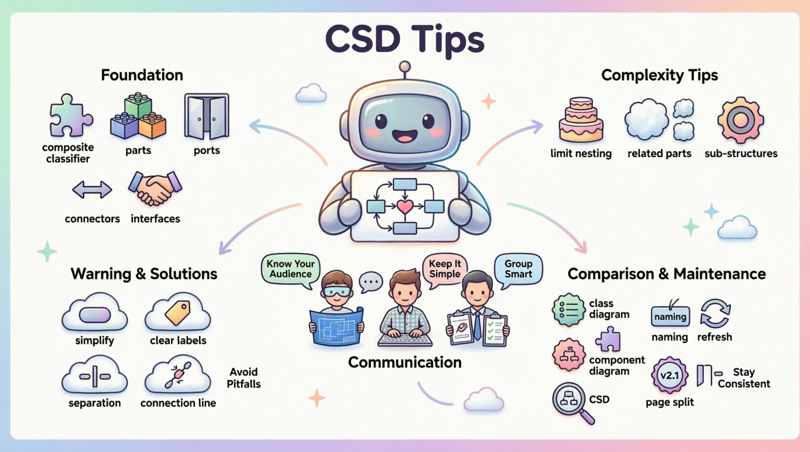
- Composite Classifiers: These represent the container or the whole entity. They act as the boundary for the internal structure.
- Parts: Parts are the components that make up the composite classifier. They are the specific instances or roles defined within the whole.
- Ports: Ports define the interaction points of a part. They specify where a part connects to the outside world or other internal parts.
- Connectors: Connectors link ports together. They establish the flow of data or control signals between components.
- Interfaces: Interfaces define the contract for interaction. They specify what operations a part must support without detailing the implementation.
When modeling these elements, clarity is paramount. Avoid combining multiple roles into a single visual element unless absolutely necessary. Distinct parts should have distinct visual identities. This separation helps readers track responsibilities during the analysis phase.
📊 Managing Internal Complexity
One of the primary challenges in composite structure diagrams is managing depth. As systems grow, the internal structure can become nested and difficult to follow. Excessive nesting obscures the primary relationships. To mitigate this, apply the following structural strategies.
1. Limit Nesting Depth
Deep nesting creates a visual hierarchy that is hard to scan. A composite structure diagram should ideally not exceed three levels of nesting. If a part requires further internal breakdown, consider creating a separate diagram for that specific part. This approach keeps the main diagram focused on high-level interactions.
2. Group Related Parts
Use frames or compartments to group related parts together. This visual cue indicates that these elements function as a cohesive unit. For example, if a server contains multiple database instances, group them under a logical label. This reduces the visual noise of individual connectors.
3. Leverage Sub-Structures
When a specific internal configuration is reused across multiple composite classifiers, define it as a sub-structure. This promotes consistency and reduces redundancy. If the internal layout of a module does not change, reference the sub-structure rather than redrawing it every time.
🗣️ Enhancing Stakeholder Communication
The primary goal of a composite structure diagram is communication. It serves as a bridge between technical architects and development teams. Different audiences require different levels of detail. Tailoring the diagram to the reader ensures the information is absorbed correctly.
- For Architects: Focus on the high-level flow and integration points. Show how major subsystems connect. Omit implementation-level details unless they impact the architecture.
- For Developers: Include specific port types and interface definitions. They need to know how to instantiate parts and where to inject dependencies.
- For Project Managers: Highlight the logical boundaries and major components. They need to understand the scope of the internal structure without getting lost in syntax.
Consistency in notation is vital for all audiences. If a specific shape represents a database component, it must represent a database component throughout the entire model. Inconsistent visual language forces the reader to constantly re-interpret the meaning, slowing down the review process.
⚠️ Common Modeling Errors to Avoid
Even experienced modelers can fall into traps that reduce the utility of a composite structure diagram. Recognizing these pitfalls early saves time during the design phase. Below are common mistakes and how to correct them.
| Pitfall | Impact | Solution |
|---|---|---|
| Over-complication | Readers cannot see the big picture. | Simplify by removing non-essential internal parts. |
| Ambiguous Ports | Confusion about data flow direction. | Clearly label provided and required interfaces. |
| Mixed Contexts | Blending logical and physical structures. | Keep logical structure separate from physical deployment. |
| Missing Connectors | Parts appear isolated without interaction. | Ensure all critical interactions have explicit connectors. |
Another frequent error is confusing the composite structure with the component diagram. While similar, the composite structure focuses on the internal composition of a single classifier. A component diagram shows the relationships between different components in the system. Mixing these contexts leads to confusion regarding scope and responsibility.
🔍 Comparison: CSD vs. Other Diagrams
Selecting the right diagram type is crucial for effective documentation. The composite structure diagram is not a replacement for every other modeling artifact. It fills a specific niche regarding internal structure. Understanding when to use it versus other diagrams ensures the model remains coherent.
- Class Diagram: Focuses on attributes and methods of classes. Use this for data structure and static relationships.
- Component Diagram: Shows the deployment and dependency of components. Use this for system integration and physical architecture.
- Composite Structure Diagram: Focuses on the internal parts and their collaboration. Use this when the internal composition of a class or component is complex.
Use the composite structure diagram when the question is “What makes up this specific object?” rather than “How does this object relate to others?” This distinction keeps the model focused and prevents redundancy.
🛠️ Best Practices for Maintenance
Diagrams are living documents. They evolve as the system changes. Maintaining a composite structure diagram requires discipline. Without regular updates, the documentation becomes a source of misinformation. Adhere to the following maintenance guidelines.
- Standardize Naming Conventions: Use consistent prefixes for parts and ports. For instance, prefix all ports with “Port_” to distinguish them from classes.
- Review Interface Definitions: Regularly check if the interfaces used by parts still match the requirements. Outdated interfaces lead to implementation errors.
- Version Control: Treat diagram files like code. Use version control to track changes to the structure over time.
- Limit Scope per Page: Do not cram the entire system onto one canvas. Split large structures into logical sections.
Documentation hygiene is as important as the design itself. A clean diagram is easier to validate and easier to update. Invest time in organizing the canvas space. Use white space effectively to separate distinct functional areas. Cluttered diagrams often lead to missed requirements during the review process.
🚀 Advanced Structural Techniques
For complex systems, standard modeling might not suffice. Advanced techniques allow for more granular control over the representation. These methods help when dealing with highly dynamic or flexible architectures.
Dynamic Parts: Some parts are created or destroyed at runtime. While static diagrams usually represent the static structure, you can annotate parts to indicate dynamic creation. This informs developers that lifecycle management is required.
Virtual Parts: In some cases, a part represents a resource that is not explicitly instantiated. Use this sparingly to represent external dependencies or abstract resources. Clearly label these to avoid confusion with concrete components.
Collaboration Roles: Sometimes a part plays multiple roles. Use the role notation to indicate that a single part can interact with different interfaces depending on the context. This reduces the need for duplicate parts in the diagram.
🔗 Ensuring Consistency Across Models
A composite structure diagram should align with the rest of the system model. Inconsistencies between diagrams create gaps in understanding. The relationships defined here must match the class diagram and component diagram.
- Attribute Alignment: Ensure attributes defined in the class diagram match the properties of the parts in the composite diagram.
- Interface Consistency: Operations defined in the interface should be present in the parts that implement them.
- Relationship Mapping: Associations in the class diagram should have corresponding connectors in the composite structure.
Regular synchronization sessions between modelers are recommended. If one diagram changes, others should be updated to reflect the new reality. This practice ensures the system documentation remains a single source of truth.
📝 Final Thoughts on Hierarchy Management
Simplifying complex hierarchies is a continuous process. It requires balancing detail with clarity. The composite structure diagram is a powerful tool for revealing the inner workings of a system. By adhering to these tips, you create models that are robust and communicative.
Focus on the relationships that matter. Ignore the noise. Keep the structure shallow where possible. Use clear labels and consistent notation. These habits lead to better design outcomes. When the diagram is clear, the implementation is clearer. This alignment reduces risk and accelerates development cycles.
Apply these principles to your next modeling task. Start by auditing your current diagrams against these guidelines. Identify areas of excessive nesting or ambiguity. Refine the structure to improve readability. The effort invested in clarity pays off during the construction and maintenance phases.