


UML sequence diagrams serve as the visual backbone for understanding system interactions over time. They map out how objects communicate, the order of operations, and the flow of data within a software architecture. However, a diagram that looks correct is not necessarily a diagram that works. Ambiguity in modeling can lead to significant implementation errors, technical debt, and misunderstood requirements during the development lifecycle. 🛠️
Validation is the process of verifying that your diagram accurately represents the intended system behavior while adhering to standard notation rules. This guide provides a rigorous framework for reviewing your interaction diagrams. By following this checklist, you ensure that the model is syntactically correct, logically sound, and ready for stakeholders to review.
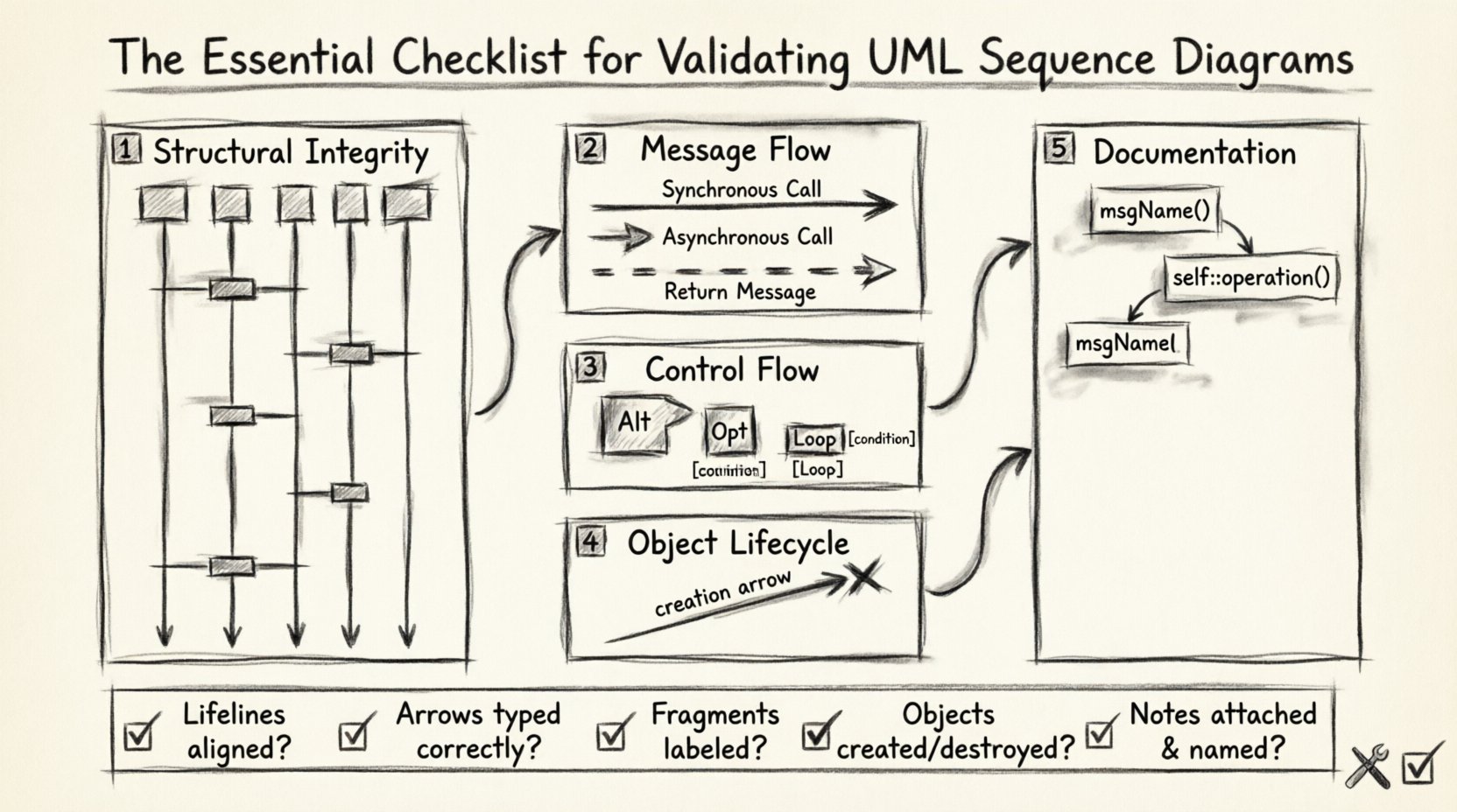
1. Structural Integrity and Participant Setup 🏗️
The foundation of any sequence diagram is the participants and lifelines. These elements define the actors, objects, or systems involved in the interaction. Before examining the messages, you must verify the structural components.
Participants and Lifelines
- Name Consistency: Ensure every participant name matches the class or interface definition in your class diagram. Inconsistencies here cause confusion regarding which entity is performing the action.
- Correct Type: Verify if the participant is an Actor, a Boundary, an Entity, or a Control. The stereotype notation (e.g., <<boundary>>) should be accurate.
- Lifeline Presence: Every participant must have a vertical dashed line extending downward from the activation bar or top of the diagram.
- Top Alignment: All lifelines must originate from the same horizontal baseline at the top of the diagram to indicate they exist at the start of the interaction.
Activation Bars
Activation bars (or focus of control) indicate the period during which an object is performing an action. They are critical for understanding concurrency and processing time.
- Start and End: An activation bar must start when a message is received and end when the object completes its task or sends a return message.
- Self-Invocation: If an object calls itself, the activation bar must overlap or extend to show the object is still processing.
- Concurrent Processing: Multiple activation bars on the same lifeline indicate parallel processes, which must be explicitly managed in the model.
2. Message Semantics and Flow Direction 📬
Messages represent the communication between participants. The type of arrow used conveys specific timing and dependency information. Misinterpreting these arrows can lead to race conditions or blocking behavior in the code.
Arrow Types
- Synchronous (Solid Arrowhead): The sender waits for a response before continuing. This is the default for method calls in many languages.
- Asynchronous (Open Arrowhead): The sender continues execution immediately after dispatching the message. Use this for fire-and-forget scenarios.
- Return Message (Dashed Line): Every synchronous call should ideally have a corresponding return message, unless the operation is void or the return is implicit.
- Signal (Dashed Arrowhead): Used for events where the sender does not expect a return signal immediately.
Message Ordering
The vertical position of messages on the diagram dictates the sequence of execution.
- Chronological Order: Messages must flow from top to bottom. A message cannot appear above the message that triggered it unless it is a return message.
- Execution Path: Trace the path from the initiating actor to the final response. Ensure there are no dead ends where a message is sent but never returned or processed.
- Context Switching: If a message is sent to a remote system, verify if the latency is represented or if the diagram assumes immediate availability.
3. Control Flow Fragments and Logic Guards 🔄
Real-world systems are rarely linear. They contain loops, conditional branches, and optional steps. UML supports this through interaction fragments.
Fragment Types
- Alt (Alternative): Represents if-else logic. Ensure that the guard conditions (e.g., [condition]) cover all possibilities to avoid gaps in logic.
- Opt (Optional): Represents an optional interaction. The guard condition should be clear about when this path is taken.
- Loop: Used for iteration. Specify the iteration count or condition (e.g., [while x > 0]). Ensure the loop has a clear exit condition.
- Break: Indicates an early exit from a loop or fragment.
Guard Conditions
Guard conditions define the truth value required for a path to be taken.
- Clarity: Guards should be descriptive. Avoid vague terms like “if true.” Use specific data states, such as [user is authenticated] or [inventory > 0].
- Completeness: If using Alt fragments, ensure all logical paths are accounted for. If one branch is missing, the model implies a runtime error.
- Nesting: Avoid excessive nesting of fragments. Deeply nested logic makes the diagram difficult to read and validate.
4. Object Lifecycle and Creation/Destruction 🔄
Objects do not always exist for the duration of the interaction. Some are created dynamically, while others are destroyed after use. Modeling this lifecycle correctly prevents memory leaks and initialization errors in the design phase.
Creation and Destruction
- Creation Message: When a new object is instantiated, use a special message arrow (often a dashed line with a specific symbol) originating from the creator.
- Destruction Message: When an object is no longer needed, mark the end of its lifeline with an “X” symbol.
- Lifetime Scope: Ensure objects are not referenced after they have been destroyed. This often happens when a response message tries to call a destroyed object.
Self-Messages
Objects often invoke their own operations.
- Looping: Self-messages can create recursive loops. Validate that the recursion has a base case to prevent infinite loops.
- Activation: Ensure the activation bar extends to show the object is busy during the self-invocation.
5. Documentation and Clarity Standards 📝
A diagram is a communication tool. If it is not understandable by a human, it fails its primary purpose. Clarity standards ensure that the diagram remains maintainable as the system evolves.
Notes and Annotations
- Clarification: Use notes for information that does not fit into the flow, such as error handling strategies or external dependencies.
- Linking: Ensure notes are attached to the specific lifeline or message they describe.
- Constraints: Use text constraints for non-functional requirements, such as [timeout: 5s] or [security: TLS 1.2].
Naming Conventions
- Verbs for Messages: Message names should be action-oriented (e.g., calculateTotal, validateUser) rather than nouns.
- LowerCamelCase: Adhere to a consistent naming convention for variables and objects to reduce cognitive load.
- No Abbreviations: Avoid abbreviations unless they are industry standard. Ambiguity kills collaboration.
Common Errors and Corrections Table 🛠️
| Issue Category | Common Error | Correction Strategy |
|---|---|---|
| Message Flow | Missing return arrow | Add dashed return arrow to complete the call stack. |
| Logic | Alt fragment without else | Add a default guard condition [else] to cover all cases. |
| Objects | Reference to destroyed object | Move the message before the destruction point or create a new instance. |
| Timing | Asynchronous message treated as synchronous | Verify if the sender waits. If not, change arrow to open head. |
| Clarity | Vague guard conditions | Replace with specific data state checks. |
Validation Criteria Matrix 📊
Use this matrix to track the status of your validation process during the review phase.
| Check Item | Pass Criteria | Review Status |
|---|---|---|
| Lifeline Alignment | All lifelines start at the same vertical level. | ⬜ |
| Message Types | Arrowheads match the communication protocol. | ⬜ |
| Fragment Logic | All paths are accounted for in Alt/Opt blocks. | ⬜ |
| Object Lifecycle | No references after destruction point. | ⬜ |
| Activation Bars | Bars align with message receipt and completion. | ⬜ |
| Readability | Labels are descriptive and consistent. | ⬜ |
Maintenance and Iteration 🔄
Validation is not a one-time event. Software requirements change, and the diagrams must evolve to reflect the new state of the system. Regular reviews prevent the diagram from becoming obsolete.
Version Control
- Traceability: Link diagram versions to specific requirements or user stories.
- Change Log: Document why a specific interaction was modified. This aids in debugging future issues.
- Baseline: Establish a baseline version of the diagram for the release cycle.
Feedback Loops
Developers and architects should review diagrams before coding begins. This ensures that the implementation plan aligns with the design intent. If a developer finds a logical gap during implementation, the diagram should be updated immediately to reflect the reality of the code.
Tooling and Automation
While manual review is essential, some validation steps can be automated. Check for syntax errors using modeling parsers. Ensure that generated code matches the diagram structure. If the code deviates significantly, the diagram needs to be corrected.
Summary of Best Practices ✅
Validating UML sequence diagrams requires a disciplined approach. It is not enough to simply draw the lines; you must verify the logic, timing, and lifecycle of every element involved. By systematically checking structural integrity, message semantics, control flow, object lifecycle, and documentation standards, you create a model that serves as a reliable contract between design and implementation.
Keep these principles in mind:
- Ensure lifelines and participants are correctly defined.
- Verify that message arrows accurately reflect timing (sync vs async).
- Check that all logical branches (Alt/Opt) are covered.
- Confirm that objects are not used after they are destroyed.
- Maintain clear naming and documentation throughout the diagram.
Adhering to this checklist reduces the risk of miscommunication and ensures that your system architecture is built on a solid foundation of verified interactions. Regular validation keeps the documentation accurate and the development process efficient.