Software architecture relies heavily on visual communication. When building complex systems, relying solely on text or code snippets often leads to misunderstandings between stakeholders, developers, and architects. Unified Modeling Language (UML) provides a standardized set of notations to represent these systems. However, the ecosystem contains over fourteen types of diagrams. Choosing the wrong visualization tool can obscure critical information rather than clarify it.
Among these tools, the UML Sequence Diagram stands out for illustrating dynamic behavior. It captures how objects interact over time. Yet, many teams struggle to decide when to deploy a sequence diagram versus other options like activity diagrams, class diagrams, or use case diagrams. This guide provides a detailed examination of the sequence diagram and how it compares to its peers, helping you select the right tool for specific design challenges.
Understanding the UML Sequence Diagram 🧵
A UML Sequence Diagram is a type of interaction diagram. It focuses on the time-ordered flow of messages between participants. Unlike structural diagrams that show static relationships, sequence diagrams depict dynamic processes. They are essential for understanding the logic of a specific operation within a larger system.
The core components of a sequence diagram include:
- Lifelines: Vertical dashed lines representing objects, actors, or system components.
- Messages: Arrows indicating communication between lifelines. These can be synchronous (blocking), asynchronous (non-blocking), or return messages.
- Activation Bars: Rectangles on lifelines showing when an object is active and performing an action.
- Combined Fragments: Boxes defining control structures like loops, alternatives, or parallel interactions.
When you draw a sequence diagram, you are essentially telling a story about a specific event. For example, “How does a user login?” The diagram maps the path from the initial trigger to the final response. This temporal focus distinguishes it from other UML artifacts.
The Landscape of UML Diagrams 🗺️
To understand where the sequence diagram fits, we must look at the broader classification of UML diagrams. They are generally divided into two categories: structural and behavioral.
- Structural Diagrams: These show the static parts of the system. They define the anatomy, such as classes, objects, and components.
- Behavioral Diagrams: These show the dynamic parts. They define the actions, states, and interactions that occur during runtime.
The sequence diagram belongs to the behavioral category, specifically within the interaction sub-category. Other behavioral diagrams include activity diagrams and state machine diagrams. Structural diagrams include class diagrams and component diagrams. Knowing this distinction helps narrow down your choices based on whether you need to show structure or behavior.
Sequence Diagram vs. Use Case Diagram 🆚
Both diagrams are often used during the early requirements phase, but they serve different purposes. A common point of confusion is whether to map out user goals or map out the system logic.
Use Case Diagrams 🎯
A use case diagram focuses on functionality from the user’s perspective. It identifies actors (users or external systems) and the goals they want to achieve. It is high-level and does not show the internal mechanics.
- Best Used For: Defining scope, identifying stakeholders, and outlining functional requirements.
- Key Elements: Actors, use cases (ovals), and relationships (includes, extends, generalization).
- Limitations: It does not show the order of steps or the internal object interactions required to complete the use case.
Sequence Diagrams ⏱️
In contrast, the sequence diagram dives into the “how.” Once a use case is identified, the sequence diagram details the steps required to fulfill it. It shows the internal system calls triggered by the actor.
- Best Used For: Designing specific functions, documenting APIs, and debugging interaction flows.
- Key Elements: Objects, messages, timing, and control flow.
- Limitations: It can become cluttered if you try to map every possible scenario for a large system.
Comparison Table: Use Case vs. Sequence
| Feature | Use Case Diagram | Sequence Diagram |
|---|---|---|
| Focus | What the system does (Functionality) | How the system does it (Interaction) |
| Level of Detail | High-level, abstract | Low-level, concrete |
| Time Dimension | None | Explicit (Vertical Axis) |
| Primary Audience | Stakeholders, Business Analysts | Developers, Architects |
Sequence Diagram vs. Activity Diagram 🔄
Activity diagrams are often compared to sequence diagrams because both describe behavior. However, they visualize flow differently.
Activity Diagrams 📝
An activity diagram resembles a flowchart. It focuses on the control flow of a system. It is excellent for showing decision points, parallel processing, and the overall workflow of a process. It does not strictly require objects; it focuses on actions.
- Best Used For: Modeling business processes, complex algorithmic logic, and parallel execution paths.
- Strengths: Great for visualizing loops, conditional logic (if/else), and concurrency.
Sequence Diagrams 🧩
Sequence diagrams focus on the objects involved in the process. While activity diagrams show the steps, sequence diagrams show which parts of the system execute those steps.
- Best Used For: Showing the interaction between specific classes or services.
- Strengths: Ideal for API design and understanding the lifecycle of an object during a specific transaction.
If you need to know the order of operations without caring about the specific objects, use an activity diagram. If you need to know which service handles which request, use a sequence diagram. Often, architects use both: the activity diagram for the business flow and the sequence diagram for the technical implementation.
Sequence Diagram vs. Class Diagram 🏗️
This is perhaps the most critical comparison. The class diagram defines the blueprint, while the sequence diagram defines the construction activity.
Class Diagrams 🏛️
A class diagram is a structural diagram. It shows the classes, their attributes, methods, and the relationships between them (inheritance, association, aggregation). It is static. It does not change based on runtime events.
- Best Used For: Database schema design, defining data models, and establishing the static architecture.
- Key Elements: Classes, attributes, methods, associations.
Sequence Diagrams ⚡
The sequence diagram relies on the class diagram. You cannot draw a sequence diagram without knowing what classes exist. However, the sequence diagram shows how those classes work together dynamically.
- Best Used For: Validating that the class structure supports the required interactions.
- Key Elements: Interactions, message passing, temporal constraints.
If a class diagram shows that a User class has a relationship with an Order class, the sequence diagram shows the moment when a User creates an Order object and sends data to it. Using both ensures that the static structure can actually support the dynamic behavior.
Sequence Diagram vs. State Machine Diagram ⚙️
State machine diagrams are often overlooked but are vital for objects with complex lifecycles.
State Machine Diagrams 🔄
This diagram tracks the state of a single object over time. It shows how an object transitions from one state to another based on events.
- Best Used For: Objects with distinct states (e.g., an Order that is Pending, Shipped, or Cancelled).
- Key Elements: States, transitions, events, guards.
Sequence Diagrams 📉
A sequence diagram tracks the interaction between multiple objects. While a state machine diagram looks deep at one object, a sequence diagram looks wide at the system.
- Best Used For: System-wide workflows involving multiple components.
- Key Elements: Multiple lifelines, message flow.
Consider an e-commerce system. A state machine diagram would define the lifecycle of a single product item. A sequence diagram would define the entire checkout process involving the cart, payment gateway, and inventory service. They are complementary tools.
Sequence Diagram vs. Communication Diagram 🗣️
These two diagrams are technically part of the same family (interaction diagrams) and contain similar information. The difference lies in the emphasis of the presentation.
Communication Diagrams 🤝
Formerly known as collaboration diagrams, communication diagrams emphasize the structural organization of objects. They show how objects are linked together to pass messages. The order of messages is indicated by numbering, not vertical position.
- Best Used For: Showing the topology of the system and how objects are connected.
- Key Elements: Objects, links, numbered messages.
Sequence Diagrams 📅
Sequence diagrams emphasize the chronological order. The vertical axis is time. It is easier to see which message happens first.
- Best Used For: Showing complex timing, delays, and sequential dependencies.
- Key Elements: Lifelines, time ordering.
If you need to debug a race condition or understand the exact timing of a response, the sequence diagram is superior. If you need to understand the network topology of your services, the communication diagram is often clearer.
Decision Matrix for Diagram Selection 🧠
To simplify the selection process, consider the following matrix. It helps identify the right tool based on your specific goal.
| Goal | Recommended Diagram | Why? |
|---|---|---|
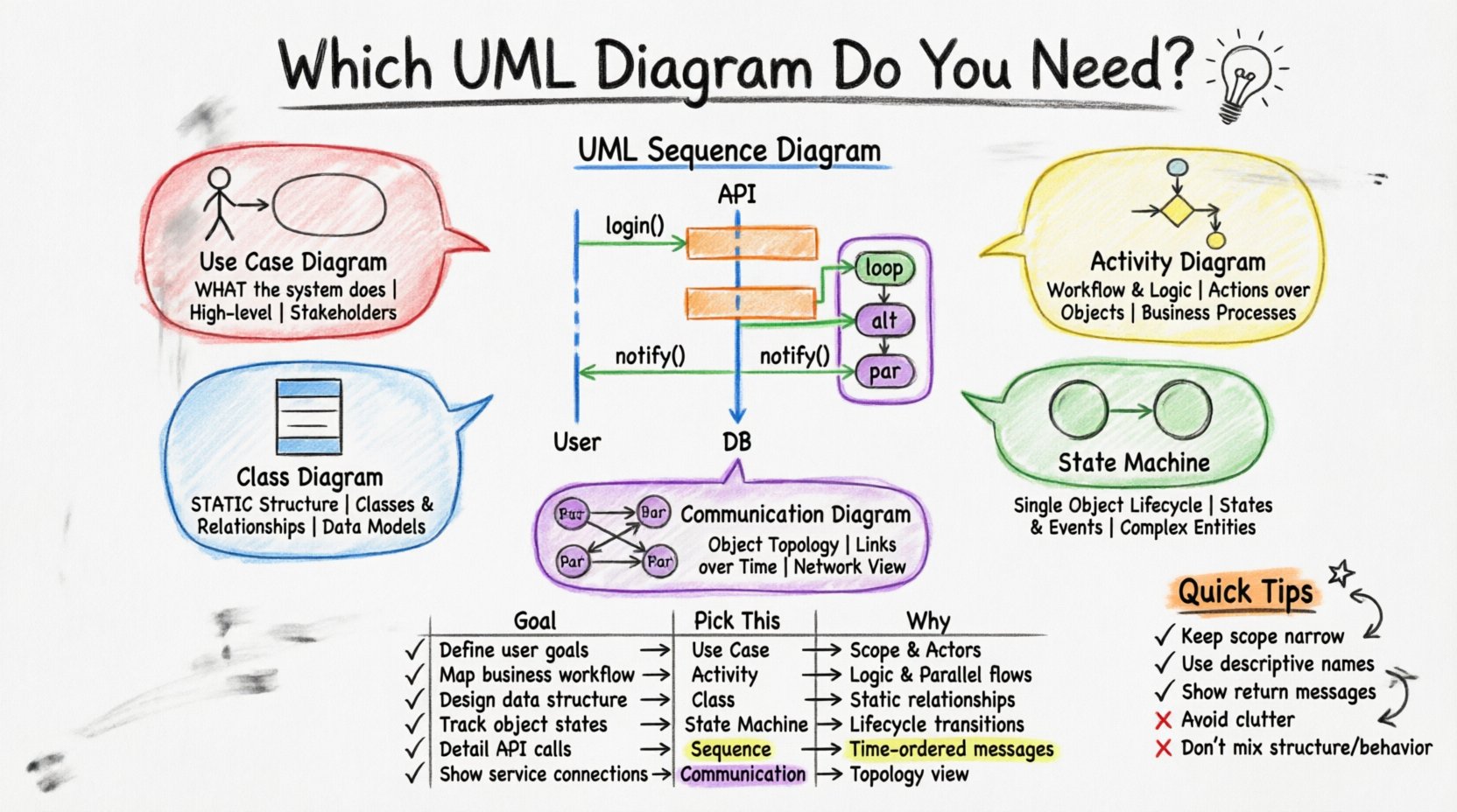
| Define User Goals | Use Case Diagram | Focuses on functionality and actors. |
| Map Business Workflow | Activity Diagram | Handles complex logic and parallel flows well. |
| Design Object Structure | Class Diagram | Defines static attributes and relationships. |
| Track Object Lifecycle | State Machine Diagram | Focuses on state transitions of a single entity. |
| Detail API Interactions | Sequence Diagram | Shows time-ordered message exchange between services. |
| Show Object Topology | Communication Diagram | Visualizes connections and object links clearly. |
Best Practices for Sequence Diagrams ✍️
Creating effective sequence diagrams requires discipline. Poorly drawn diagrams can be harder to read than code. Follow these guidelines to maintain clarity.
- Keep Scope Limited: Do not attempt to map the entire system in one diagram. Focus on one use case or scenario at a time.
- Use Descriptive Names: Name your objects and messages clearly. Avoid generic terms like “Object1” or “ProcessData”.
- Standardize Message Types: Use solid arrows for synchronous calls and open arrows for asynchronous calls. This visual cue helps readers understand blocking behavior.
- Leverage Fragments: Use combined fragments for loops (
loop), conditionals (alt), and parallel processes (par). This reduces clutter compared to drawing every iteration. - Minimize Lifelines: Only include objects that participate in the specific interaction. Excess lifelines create noise.
- Focus on Critical Paths: Highlight the happy path first. Document error handling in separate diagrams or using specific fragment types.
Common Mistakes to Avoid ⚠️
Even experienced architects make errors when modeling interactions. Being aware of these pitfalls can save time during reviews.
- Mixing Structure and Behavior: Do not try to show class attributes inside a sequence diagram. Keep structural details in the class diagram.
- Over-Abstraction: If you hide too many details, the diagram becomes useless for developers. If you show too many, it becomes unreadable. Find the balance.
- Ignoring Return Messages: Always show the return path. It indicates that the system successfully processed the request.
- Unclear Actors: Ensure external actors are clearly distinguished from internal system objects. Use standard stick figures for human actors.
- Static Data in Dynamic Flows: Do not list database fields or variable names unless they are critical to the message flow. Keep the focus on the interaction.
Integrating Diagrams into the Workflow 🔄
Diagramming is not a one-time task. It should be integrated into the development lifecycle. When you start a new feature, define the scope with a use case diagram. Design the data model with a class diagram. Detail the interaction with a sequence diagram. Finally, verify the workflow logic with an activity diagram if necessary.
This layered approach ensures that every aspect of the system is documented appropriately. The sequence diagram acts as the bridge between the static design (classes) and the dynamic execution (activity/workflow). It translates the “what” of the requirements into the “how” of the implementation.
Technical Considerations for Implementation 🛠️
When implementing the logic shown in a sequence diagram, developers must adhere to the defined contracts. If the diagram specifies a synchronous call, the code must block until a response is received. If it specifies an asynchronous event, the code should fire and forget.
Refactoring often impacts sequence diagrams. If you move a method from one class to another, the sequence diagram must be updated. This is a key reason why diagrams can become outdated. To mitigate this, consider using tools that generate diagrams from code or vice versa, though manual review is still essential for architectural decisions.
Final Thoughts on Visual Clarity 🎨
The goal of any diagram is communication. If a stakeholder cannot understand the chart within a few minutes, the design has failed. The sequence diagram is a powerful tool for technical communication, particularly for distributed teams where asynchronous communication is common.
By understanding the strengths and weaknesses of the sequence diagram relative to other UML charts, you can ensure that your documentation supports your development goals. Use the right tool for the job, maintain clarity, and focus on the specific questions you need to answer. This disciplined approach leads to robust systems and fewer misunderstandings during the development lifecycle.