Software architecture relies heavily on communication. When multiple systems, components, or actors interact, the complexity can grow rapidly. To manage this, developers and architects use standardized notations. Among these, the Unified Modeling Language (UML) sequence diagram stands out as a critical tool for visualizing dynamic behavior. This guide provides a deep dive into the mechanics, notation, and practical application of sequence diagrams, moving from basic concepts to advanced interaction patterns.
Understanding the Core Purpose 🎯
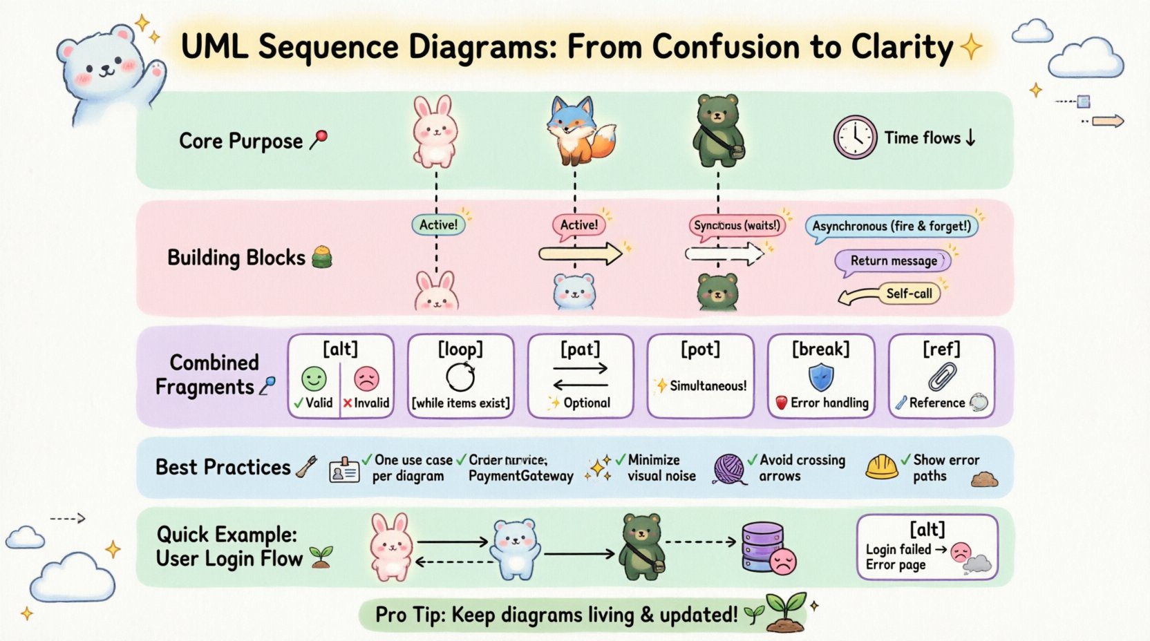
A sequence diagram is a type of interaction diagram. It shows how objects operate with one another and in what order. The primary focus is on the flow of control and data between the participants over time. Unlike class diagrams that show static structure, sequence diagrams capture the temporal aspect of a system.
Key characteristics include:
- Time Orientation: Time flows from top to bottom.
- Focus on Interactions: It highlights the exchange of messages between objects.
- Contextual Clarity: It defines the lifecycle of a specific scenario or use case.
When constructing these diagrams, the goal is to depict the logic of a system without getting bogged down in implementation details. This abstraction allows stakeholders to verify requirements and logic before writing code.
Essential Building Blocks 🧱
To read or create a sequence diagram effectively, one must understand the standard elements. Each element serves a specific semantic purpose in the diagram.
1. Participants (Lifelines) 🟦
A participant represents an entity involved in the interaction. This could be a user, a class, an interface, or an external system. In the diagram, a participant is represented by a vertical dashed line extending from the top of the page. This line is called a lifeline.
- Label: Placed at the top of the lifeline, often in bold text.
- Identity: Can represent a specific instance (e.g.,
customer: Customer) or a general class (e.g.,Customer). - Duration: The line extends downward to show how long the participant is active in the interaction.
2. Activation Bars ⏱️
Also known as execution occurrences, the activation bar is a thin rectangular box placed on the lifeline. It indicates the period during which the participant is performing an action or is in control.
- Entry Point: The top of the bar shows when an object begins processing.
- Exit Point: The bottom of the bar shows when the object finishes its task and returns control.
- Nesting: Bars can be nested to show recursive calls or long-running processes.
3. Messages 💬
Messages are horizontal arrows connecting lifelines. They represent the communication between participants. The direction of the arrow indicates the flow of information.
Message Types
| Type | Arrow Style | Semantics |
|---|---|---|
| Synchronous | Filled Arrowhead | The sender waits for the receiver to complete the task before continuing. |
| Asynchronous | Open Arrowhead | The sender fires the message and continues immediately without waiting. |
| Return | Dashed Line + Open Arrowhead | Indicates a response sent back from the receiver to the sender. |
| Self-Call | Curved Arrow | The object invokes a method on itself. |
Advanced Interaction Patterns 🔗
Real-world scenarios rarely follow a single linear path. Systems often branch, loop, or run in parallel. UML provides Combined Fragments to handle these complexities. These are enclosed in a rectangular frame labeled with a specific keyword.
1. Alt (Alternative) 🔄
Used to represent conditional logic, similar to if-else statements. It divides the interaction into multiple fragments, where only one path is executed based on a condition.
- Structure: A frame labeled
altcontaining multiple operands separated by dashed lines. - Condition: Each operand has a guard condition in square brackets (e.g.,
[user is valid]). - Usage: Essential for showing branching logic like authentication success vs. failure.
2. Opt (Optional) ⚡
Similar to alt, but implies that the fragment is optional. If the condition is false, the interaction within the fragment simply does not occur.
- Use Case: Showing optional features, such as saving a backup or logging an error.
- Condition: Typically a single condition determines if the whole block runs.
3. Loop 🔄
Represents repetition, similar to for or while loops. It is used when an action is performed multiple times.
- Label: The frame is labeled
loop. - Condition: Can specify a counter or a termination condition (e.g.,
[while items exist]). - Usage: Iterating through a list of database records or retrying a network request.
4. Break 🛑
Represents an exception path or a termination of the normal flow. It is often used to show error handling.
- Structure: Enclosed in a frame labeled
break. - Condition: Usually indicates an error state (e.g.,
[timeout occurs]).
5. Par (Parallel) ☎️
Indicates that multiple operations occur simultaneously. This is common in systems with multithreading or distributed microservices.
- Structure: The frame is labeled
par. - Execution: All interactions within the frame happen at the same time.
- Usage: Showing a system sending data to both a database and a cache simultaneously.
6. Ref (Reference) 📎
Used to reference another sequence diagram or a detailed section of the current diagram. It keeps the main diagram clean by hiding complexity.
- Label: The frame is labeled
ref. - Link: Points to a specific diagram name or a section within the same model.
Best Practices for Effective Design 🛠️
Creating a clear diagram requires discipline. A cluttered diagram is worse than no diagram at all. Adhering to established guidelines ensures the documentation remains useful for future maintenance.
1. Scope Management
Do not attempt to diagram the entire system in one view. A single sequence diagram should focus on a single use case or a specific interaction flow. If the scenario is complex, use the Ref fragment to break it down into sub-diagrams.
2. Naming Conventions
Consistency is key. Use meaningful names for participants and messages.
- Participants: Use class names or specific roles (e.g.,
OrderService,PaymentGateway). - Messages: Use verb phrases that describe the action (e.g.,
processPayment(),sendConfirmation()).
3. Minimize Activation Bars
Only draw activation bars where necessary. If an object is simply passing a message along without processing, an activation bar might be omitted to reduce visual noise. This keeps the focus on the critical decision points.
4. Logical Ordering
Arrange messages in a logical sequence. Avoid crossing arrows where possible. Crossing lines create visual confusion and make it harder to trace the flow of control.
5. Handling Exceptions Explicitly
Do not ignore error paths. Use the Break or Alt fragments to show what happens when a service fails. This is crucial for understanding system resilience.
Common Pitfalls to Avoid 🚫
Even experienced practitioners make mistakes when designing these diagrams. Recognizing these patterns early can save significant time during code reviews.
- Overloading the Diagram: Trying to show every single method call makes the diagram unreadable. Focus on the high-level flow.
- Ignoring Time: The vertical axis represents time. Ensure that messages sent from the bottom of a lifeline do not precede the messages sent from the top unless it is a specific asynchronous pattern.
- Missing Return Messages: While not always required for every step, omitting return messages for critical data retrieval can obscure the data flow.
- Inconsistent Notation: Mixing solid and dashed arrows arbitrarily can confuse the reader about whether a call is synchronous or asynchronous.
Reading Sequence Diagrams Effectively 👀
When reviewing a diagram created by a colleague, follow a systematic approach.
- Identify the Actors: Look at the top to see who is involved. Is it a user, an external API, or an internal component?
- Trace the Primary Flow: Follow the solid arrows from left to right. This is the happy path.
- Check the Frames: Look for
alt,loop, oroptframes. These define the boundaries of the logic. - Analyze the Returns: Trace the dashed arrows back to the sender. Ensure the data being returned matches the expectation of the caller.
- Verify the End State: Ensure all lifelines return to an idle state. If a bar extends to the bottom without a return, check if the process is truly complete or if it is waiting indefinitely.
Integration with Other UML Artifacts 📊
Sequence diagrams do not exist in isolation. They complement other diagrams in the UML suite.
- Use Case Diagrams: Sequence diagrams often detail the steps of a specific use case shown in a high-level use case diagram.
- Class Diagrams: The participants in a sequence diagram should correspond to classes defined in the class diagram. If a participant appears in a sequence but not a class diagram, it indicates a missing model element.
- State Machine Diagrams: While sequence diagrams show interaction, state diagrams show the internal behavior of a single object. Together, they provide a complete picture of object lifecycle.
Practical Example: User Login Flow 🚪
Consider a standard authentication scenario. The flow involves a user, a frontend controller, an authentication service, and a database.
- User submits credentials to Frontend.
- Frontend sends a
validateLogin()request to AuthService. - AuthService queries the Database for user details.
- Database returns user hash to AuthService.
- AuthService compares hash and returns
isValidto Frontend. - Frontend redirects based on result.
This linear flow can be expanded with an alt fragment for failed authentication, showing a redirect to an error page instead of a success redirect.
Conclusion on Clarity 🌟
Mastering the visualization of system interactions is a skill that improves with practice. By adhering to standard notation and focusing on the logical flow rather than implementation details, you create documentation that serves the team effectively. The sequence diagram remains one of the most powerful tools for communicating dynamic behavior in software engineering. When constructed with care, it eliminates ambiguity and aligns the understanding of developers, testers, and stakeholders.
Remember that the diagram is a living document. As the system evolves, the diagram should be updated to reflect the current reality. This discipline ensures that the knowledge base remains accurate and valuable throughout the lifecycle of the project.