Effective system design relies heavily on clear communication. Among the various tools available to document software architecture, the UML Sequence Diagram stands out as a critical asset for visualizing interactions. For a mid-level developer, moving beyond basic implementation to understanding the lifecycle and flow of data is essential. This guide explores the fundamental principles and advanced techniques for creating sequence diagrams that are both accurate and maintainable.
When you design a system, you are not just writing code; you are defining contracts between components. A sequence diagram captures these contracts over time. It allows stakeholders to see how objects communicate, when they are active, and what triggers specific behaviors. Without a solid grasp of these diagrams, technical debt can accumulate silently, leading to integration issues later in the development cycle.
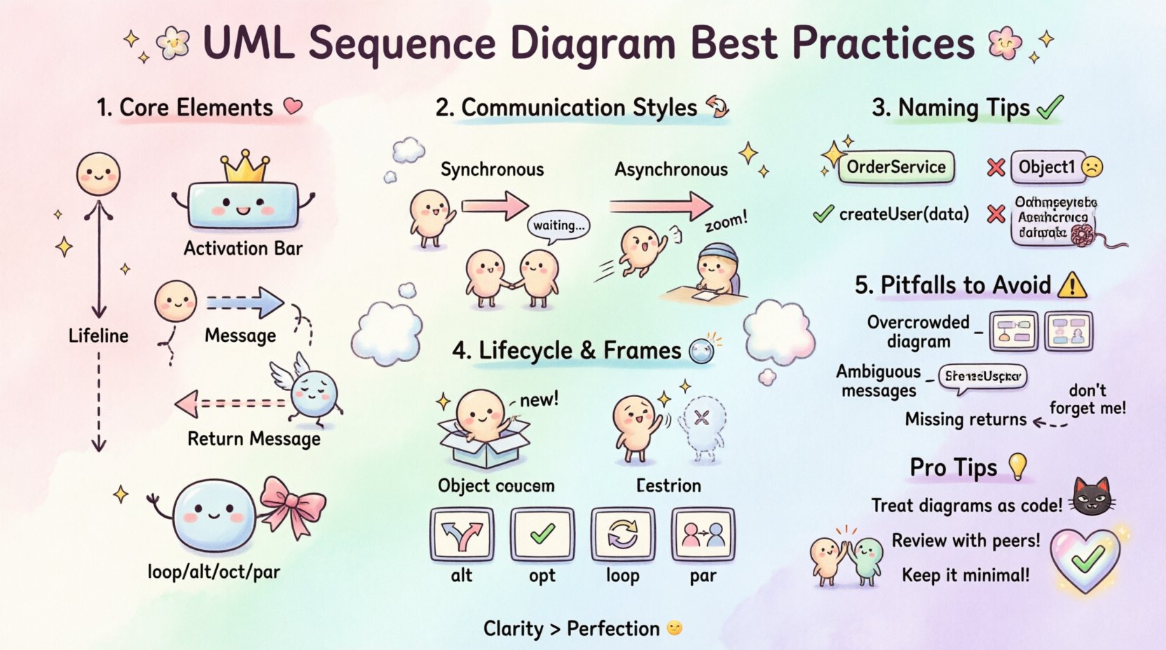
Understanding the Core Elements 🧩
Before diving into best practices, it is vital to understand the building blocks of a sequence diagram. Each element serves a specific purpose in the narrative of your system design.
- Lifelines: Represent the participants in the interaction. These can be objects, classes, or external systems. They extend vertically down the page, indicating the existence of the participant over time.
- Activation Bars: Also known as focus of control, these rectangles on a lifeline show when an object is actively performing an operation. This visual cue helps developers understand concurrency and blocking behavior.
- Messages: Arrows connecting lifelines represent method calls or signals. They are directional and define the flow of control between objects.
- Return Messages: Dashed lines indicate the return of control or data from the called object back to the caller. While often implied in code, explicitly showing them in diagrams clarifies the flow.
- Frames: Containers that define the context of a message, such as loops, conditions, or parallel processes.
Ensuring that these elements are used correctly is the first step toward professional-grade documentation. Misinterpreting a lifeline as a static component rather than a temporal entity can lead to confusion during code reviews.
Structuring Interactions Effectively 🔄
The way you structure messages determines how easily a reader can trace the logic of the system. Clarity in interaction patterns prevents ambiguity in implementation.
Synchronous vs. Asynchronous Communication
Distinguishing between synchronous and asynchronous calls is crucial for performance modeling. In a synchronous call, the caller waits for the receiver to complete the task. In an asynchronous call, the sender continues immediately without waiting.
- Synchronous Messages: Use solid lines with a filled arrowhead. This indicates that the control flow is blocked until the response is received. Use this for critical data fetching where subsequent logic depends on the result.
- Asynchronous Messages: Use solid lines with an open arrowhead. This indicates fire-and-forget behavior. Use this for logging, notifications, or background tasks that should not block the main process.
Return Messages and Data Flow
While code returns values implicitly, diagrams should make this explicit for clarity. Use dashed lines with open arrowheads for return messages. This helps stakeholders understand the volume of data being passed and the timing of the response.
For complex systems, consider grouping related messages. Instead of scattering every interaction across the page, use frames to group specific logical units. This reduces visual noise and highlights the specific scope of the interaction.
Naming and Readability 🏷️
A diagram is useless if it cannot be read quickly. Naming conventions and layout decisions directly impact the cognitive load required to understand the design.
- Object Naming: Avoid generic names like Object1 or Process2. Use domain-specific names that reflect the role of the object, such as OrderService or UserRepository. This makes the diagram self-documenting.
- Method Naming: Message labels should use standard method naming conventions. Include parameters where necessary to show data types, but keep them concise. For example, createUser(userData) is better than createUser(String name, int age, String email) unless the parameters are the focus of the interaction.
- Vertical Spacing: Maintain consistent spacing between messages. Overlapping arrows create visual clutter. If lines must cross, ensure the intersection point is clear.
- Alignment: Align lifelines logically. Group related objects together. If an object interacts frequently with another, place them closer to reduce the length of the connecting lines.
Timing and Lifecycle Management ⏱️
Understanding the lifecycle of objects within a sequence is often overlooked but vital for memory management and state consistency.
Creation and Destruction
Objects are not always present at the start of a system execution. You should explicitly show when objects are created and destroyed.
- Creation: Use a message type indicating construction (often labeled new). This clarifies where the responsibility for instantiation lies.
- Destruction: Use a cross symbol on the lifeline to indicate destruction. This is important for resource cleanup and avoiding memory leaks in the design phase.
Frames for Logic Control
Complex logic should be encapsulated within frames. This keeps the main flow clean while allowing detailed interaction logic to exist in sub-regions.
- alt (Alternative): Use this for conditional logic. Show the different paths the system can take based on a condition. Ensure conditions are clearly labeled at the top of the frame.
- opt (Optional): Use this when a message is optional. This helps in understanding error handling paths or optional features.
- loop: Use this for iterations. Label the loop condition clearly. If the loop count is unknown, this prevents confusion about infinite loops in the design.
- par (Parallel): Use this for concurrent processes. This is essential for showing multi-threaded behavior or independent subsystems working simultaneously.
Common Pitfalls to Avoid ⚠️
Even experienced developers can fall into traps that reduce the value of their diagrams. Recognizing these common mistakes early can save hours of rework.
| Issue | Why It Is Problematic | Recommended Fix |
|---|---|---|
| Overcrowding | Too many lifelines make the diagram unreadable. | Split the diagram into smaller, focused scenarios. |
| Ambiguous Messages | Messages lack context or parameter details. | Add brief descriptions or group by function. |
| Ignoring Return | Missing return messages hide data flow. | Always include return lines for clarity. |
| Mixing Concerns | Combining UI, logic, and data access in one view. | Separate diagrams by architectural layer. |
| Static Lifelines | Showing objects that do not participate in the interaction. | Remove unnecessary lifelines to focus on flow. |
By adhering to these guidelines, you ensure that the diagram remains a living document that accurately reflects the system’s behavior.
Collaboration & Documentation 🤝
A sequence diagram is rarely created in isolation. It is a tool for collaboration between developers, architects, and product managers. The way you present the diagram affects how it is received.
- Version Control: Treat diagrams as code. Store them in version control systems. This allows you to track changes over time and revert to previous designs if necessary.
- Contextual Links: Link diagrams to the relevant API specifications or database schemas. This creates a network of documentation rather than isolated images.
- Review Process: Include sequence diagrams in pull requests. Ask peers to validate the logic flow before merging code. This catches logical errors early.
- Audience Awareness: Adjust the level of detail based on the reader. A high-level view for stakeholders should focus on system boundaries. A detailed view for developers should focus on method signatures and error handling.
Maintenance Strategy 🔧
One of the biggest challenges with design documentation is keeping it up to date. When code changes, diagrams often become obsolete, leading to a loss of trust in the documentation.
- Diagram as Code: Consider using text-based diagramming tools. These allow you to generate diagrams from source files, ensuring that the visual representation matches the implementation.
- Synchronization: Schedule regular reviews of your diagrams during sprint planning. Update them alongside feature development to maintain accuracy.
- Deprecation: Mark obsolete diagrams clearly. Do not delete them immediately; instead, archive them with a note explaining why they are no longer relevant.
- Minimal Viable Diagrams: Do not document every single method call. Focus on critical paths and complex interactions. Simplify the diagram to reduce maintenance overhead.
Maintaining high-quality documentation requires discipline. It is a continuous process rather than a one-time task. By integrating diagram updates into your development workflow, you ensure that the documentation remains a valuable asset.
Advanced Scenarios 🚀
As you gain proficiency, you will encounter more complex scenarios that require nuanced handling in your diagrams.
Exception Handling
Standard flows rarely cover all edge cases. You should explicitly show how exceptions are handled in the sequence.
- Use alt frames to separate normal execution from error handling.
- Label exception messages clearly (e.g., throw Exception).
- Show how the caller recovers from the error (retry, fallback, or termination).
Timeouts and Delays
In distributed systems, timing is critical. Visualizing delays helps in understanding latency issues.
- Use dashed lines to represent time passing without interaction.
- Label the duration if it is significant (e.g., timeout(5s)).
- Show cancellation messages if a process is aborted due to timeout.
State Transitions
While state diagrams are better for complex state logic, sequence diagrams can hint at state changes.
- Highlight when an object changes its internal state significantly.
- Use comments to annotate state changes that are not obvious from the method call.
- Ensure the order of state transitions is logical and follows the interaction flow.
Final Thoughts on Design Integrity
Creating sequence diagrams is more than drawing arrows; it is about modeling the behavior of your system with precision. For a mid-level developer, mastering these practices signals a transition from writing code to designing solutions. It demonstrates an ability to think about the system as a whole rather than just individual methods.
By focusing on clear structure, precise naming, and regular maintenance, you ensure that your diagrams remain relevant. They become a reliable reference for onboarding new team members and for debugging complex issues in production. The effort invested in high-quality documentation pays dividends in reduced technical debt and smoother collaboration.
Remember, the goal is not perfection but clarity. A diagram that is slightly incomplete but easy to understand is better than a perfect one that is too complex to read. Continuously refine your approach based on feedback from your peers and the evolving needs of your project.
Adopt these practices consistently, and you will find that your system designs become more robust and your team communication more effective. The discipline required to maintain these standards separates a competent developer from a truly effective engineer.