Designing software architecture relies heavily on clear communication between technical teams. UML sequence diagrams serve as the blueprint for these interactions, mapping out how objects or systems communicate over time. However, creating a diagram is often easier than ensuring its accuracy. When messages flow incorrectly or lifelines behave unexpectedly, the entire design foundation can become shaky. This guide provides a deep dive into identifying, diagnosing, and resolving common issues within sequence diagrams.
Whether you are refining a legacy system or designing a new microservice architecture, understanding the nuances of sequence diagram syntax and logic is critical. Errors here can lead to misaligned code implementations, integration failures, and significant rework. We will explore the anatomy of these diagrams, common pitfalls, validation strategies, and methods to ensure your diagrams accurately reflect the intended system behavior.
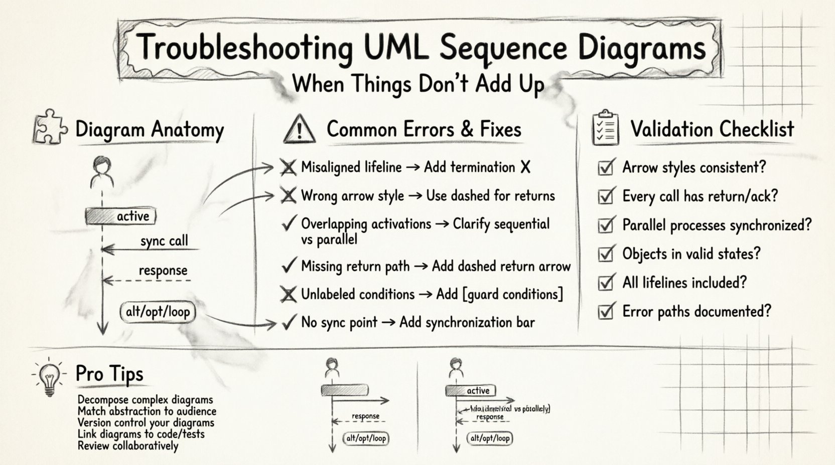
🧩 Understanding the Anatomy of a Sequence Diagram
Before troubleshooting, one must understand the standard components that make up a sequence diagram. These elements are not just visual decorations; they carry semantic weight that defines the system’s logic.
- Lifelines: Vertical dashed lines representing an object, actor, or system component. Each lifeline indicates the existence of an entity throughout the timeline of the interaction.
- Activation Bars: Rectangles on a lifeline showing when an object is actively performing an action. This indicates control over the process.
- Messages: Arrows connecting lifelines. These represent method calls, events, or data transfers.
- Return Messages: Dashed arrows indicating a response from the receiver back to the sender.
- Combined Fragments: Boxes labeled with keywords like
alt(alternative),opt(optional), orloop(repetition) that group interactions.
If any of these elements are misused, the diagram loses its ability to convey precise timing and logic. A misplaced activation bar can suggest an object is busy when it is actually idle, leading to concurrency bugs in implementation.
⚠️ Common Structural Errors and Fixes
Structural errors are often the most visible issues. They occur when the visual representation does not adhere to the established notation standards. These errors can confuse readers who expect specific visual cues for specific behaviors.
1. Misaligned Lifelines
Lifelines must start at the top of the diagram and extend downwards. If a lifeline is broken or reappears later without a specific reason (like an object being destroyed and recreated), it creates ambiguity. Ensure that every entity involved in the interaction has a continuous vertical path.
- Issue: A lifeline stops mid-diagram without a termination symbol.
- Fix: Add a clear termination point (an X at the bottom of the bar) if the object is no longer relevant to the scenario.
2. Incorrect Arrow Styles
The style of the arrow dictates the nature of the message. Solid lines usually denote synchronous calls, while dashed lines denote returns or asynchronous signals. Mixing these up changes the meaning entirely.
- Issue: Using a solid line for a return message.
- Fix: Switch to a dashed line with an open arrowhead to indicate a return value or acknowledgment.
3. Overlapping Activation Bars
Activation bars show when an object is executing code. If bars overlap in a way that suggests simultaneous execution without proper threading or concurrency mechanisms, it implies a race condition.
- Issue: Two activation bars on different lifelines overlap perfectly without a clear parent-child relationship.
- Fix: Clarify if the execution is truly parallel. If not, adjust the timing of the messages to reflect sequential processing.
🔄 Message Flow and Logic Issues
Even with perfect syntax, the logic within the message flow can be flawed. This is where the diagram fails to represent the actual business rules or data processing steps.
1. Missing Return Paths
If a method is called, there should ideally be a response, even if it is just a null acknowledgment. Missing return messages can imply that the sender waits indefinitely for a response that never comes.
- Issue: A synchronous call is made, but no arrow returns to the caller.
- Fix: Add a dashed return arrow. If the operation is fire-and-forget, explicitly label the message as asynchronous.
2. Logical Loops and Conditions
Combined fragments like alt and loop are powerful but often misused. An alt fragment implies mutually exclusive paths. An opt fragment implies a condition that may or may not be met. A loop implies repetition.
- Issue: Using a loop where only two iterations are expected, or failing to specify guard conditions in
altblocks. - Fix: Always label the guard conditions (e.g.,
[user is logged in]). If the logic is complex, break it into separate diagrams rather than cramming it into one large fragment.
3. Circular Dependencies
Messages should generally flow in a direction that supports the execution hierarchy. Circular message flows (A calls B, B calls C, C calls A immediately) can indicate circular dependencies in the code, which are difficult to manage and test.
- Issue: A chain of messages that returns to the originator without an intermediate state change.
- Fix: Introduce an intermediary object or change the interaction model to break the cycle.
⏱️ Timing and Synchronization Problems
Sequence diagrams are time-based. The vertical axis represents the progression of time. Ignoring timing constraints can lead to race conditions or deadlock scenarios in the actual software.
1. Unresolved Latency
If a diagram shows multiple parallel processes that must complete before a subsequent step, but no synchronization point is shown, the system may hang.
- Issue: Multiple threads start, but no wait or join point exists before the next major interaction.
- Fix: Add a synchronization bar (a thick horizontal bar across the lifelines) to indicate where the process waits for all parallel tasks to finish.
2. Timing Constraints
Real-world systems often have deadlines. A message might need to arrive within 5 seconds, or a response must be generated within 100 milliseconds. Without these constraints, the diagram is abstract and potentially unsafe.
- Issue: No timing notes attached to message arrows.
- Fix: Use note objects to specify constraints like
[timeout: 5s]or[delay: 100ms].
🧠 Object State and Lifecycle Conflicts
Objects in a system have states. A sequence diagram should ideally reflect the state transitions of the primary objects involved. If an object is called to perform an action it cannot perform in its current state, the diagram is invalid.
- Issue: An object receives a message to delete itself while it is already in a closed state.
- Fix: Verify the state machine for each major object. Ensure the message is valid for the object’s current state before drawing the arrow.
1. Resource Leaks in Diagrams
Just as code can leak memory, diagrams can “leak” resources. If a connection is opened in one message but never shown as closed, it implies a persistent resource that might not be released.
- Issue: A database connection is established but no close message is shown.
- Fix: Explicitly show the release of resources in the final stages of the interaction.
📋 Validation Strategies and Checklists
Systematic review is the best way to catch errors before they reach the development phase. Use the following checklist to validate your sequence diagrams.
| Check Category | Validation Question | Action |
|---|---|---|
| Visual Syntax | Are all arrows solid or dashed correctly? | Standardize arrow styles across the document. |
| Logic Flow | Does every call have a return or acknowledge? | Add return arrows or mark as fire-and-forget. |
| Timing | Are parallel processes synchronized? | Insert synchronization bars where needed. |
| State Consistency | Are objects in valid states for the action? | Cross-reference with state diagrams. |
| Completeness | Are all required lifelines included? | Ensure external systems and actors are present. |
🤝 Collaborative Review Processes
One person rarely sees every angle of a design. Collaborative review sessions are essential for troubleshooting complex diagrams. When multiple engineers review the same diagram, they bring different perspectives on edge cases and failure modes.
- Walkthroughs: Conduct a step-by-step walkthrough of the diagram with the team. Ask each member to trace a specific message path.
- Peer Sign-off: Require a sign-off from the system architect and the lead developer before the diagram is considered final.
- Version Control: Treat diagrams like code. Keep them in version control to track changes and revert if a troubleshooting session introduces errors.
🔁 Iterative Refinement Techniques
Sequence diagrams are rarely perfect on the first draft. Iteration is a core part of the design process. Refinement involves breaking down complex interactions into smaller, more manageable sub-diagrams.
1. Decomposition
If a single diagram becomes too crowded, split it into Scenario A and Scenario B. Keep the main diagram for high-level flows and use detailed diagrams for specific complex methods.
- Benefit: Reduces cognitive load for the reader.
- Benefit: Allows for deeper focus on specific logic blocks.
2. Abstraction Levels
Not all diagrams need to show every detail. Create a System Level diagram for architecture reviews and a Component Level diagram for implementation details. Ensure the abstractions match the audience’s needs.
🔗 Integration with Code and Documentation
The ultimate goal of a sequence diagram is to inform the implementation. If the code does not match the diagram, the diagram is obsolete. This disconnect is a common source of long-term technical debt.
- Code Reviews: During code reviews, check if the actual method calls match the diagram. If they diverge, update the diagram.
- Documentation: Link diagrams to the relevant API documentation. This ensures that when a developer reads the API spec, they also understand the interaction flow.
- Test Cases: Use the diagram to generate test cases. If a message path is shown, a test should exist to verify that path.
🧪 Debugging Specific Scenarios
Here are specific scenarios where sequence diagrams frequently fail and how to address them.
1. The “Ghost” Object
Sometimes an object appears in the diagram but has no activation bars. This suggests it is passive or merely a data carrier.
- Fix: If the object is passive, consider if it needs to be a lifeline at all, or if it should be passed as a parameter in a message argument.
2. The “Infinite” Loop
A loop fragment with no exit condition shown is a red flag.
- Fix: Always specify the exit condition. Even if it is
[while true], document what breaks the loop (e.g.,[error detected]).
3. The “Missing” Error Handler
Diagrams often show the happy path. They frequently omit error handling paths.
- Fix: Add an
altfragment to show what happens when an error occurs. This ensures the system behavior under failure is documented.
🛡️ Best Practices for Maintenance
Maintaining sequence diagrams over the lifecycle of a project requires discipline. As the system evolves, diagrams must evolve with it.
- Single Source of Truth: Ensure there is only one master diagram for each major interaction. Avoid duplicate diagrams that contradict each other.
- Change Logs: Document why a diagram was changed. Did the API change? Did a business rule shift?
- Automated Checks: If possible, use tools that validate the syntax of your diagrams against the standard UML rules to catch errors automatically.
🧩 Conclusion on Diagram Integrity
Maintaining the integrity of your UML sequence diagrams is not just about drawing pretty lines. It is about ensuring that the logic, timing, and interactions of your system are clearly understood by everyone involved. By systematically troubleshooting common errors, validating against checklists, and maintaining a culture of iterative refinement, you can prevent miscommunication and build more robust software architectures.
Focus on clarity, consistency, and accuracy. When your diagrams are reliable, your development process becomes smoother, and the gap between design and implementation narrows significantly. Regular review and a willingness to refactor diagrams when requirements change will keep your documentation valuable throughout the project lifecycle.
Remember that a diagram is a contract. If it does not match the reality of the code, it is broken. Keep the contract valid, and your team will reap the benefits of clear, predictable system behavior.