
In the complex landscape of systems engineering, clarity is the most valuable asset. When defining what a system must do, rather than how it is built, SysML Use Case Diagrams provide a structured approach to functional modeling. These diagrams serve as the bridge between stakeholder needs and technical implementation. They translate high-level requirements into actionable functions that drive the design process.
This guide explores the mechanics of SysML Use Case Diagrams without relying on specific software tools. The focus remains on the language itself, the standard definitions, and the logical structure required to model system behavior effectively. By understanding the core components, engineers can ensure that system boundaries are clear, interactions are defined, and functional requirements are traceable.
Why Use Case Diagrams Matter in SysML 🧩
SysML (Systems Modeling Language) extends UML (Unified Modeling Language) to address the broader needs of systems engineering. While UML focuses heavily on software, SysML encompasses hardware, software, information, and processes. Use Case Diagrams in this context are not merely about user interfaces; they represent the functional scope of the entire system.
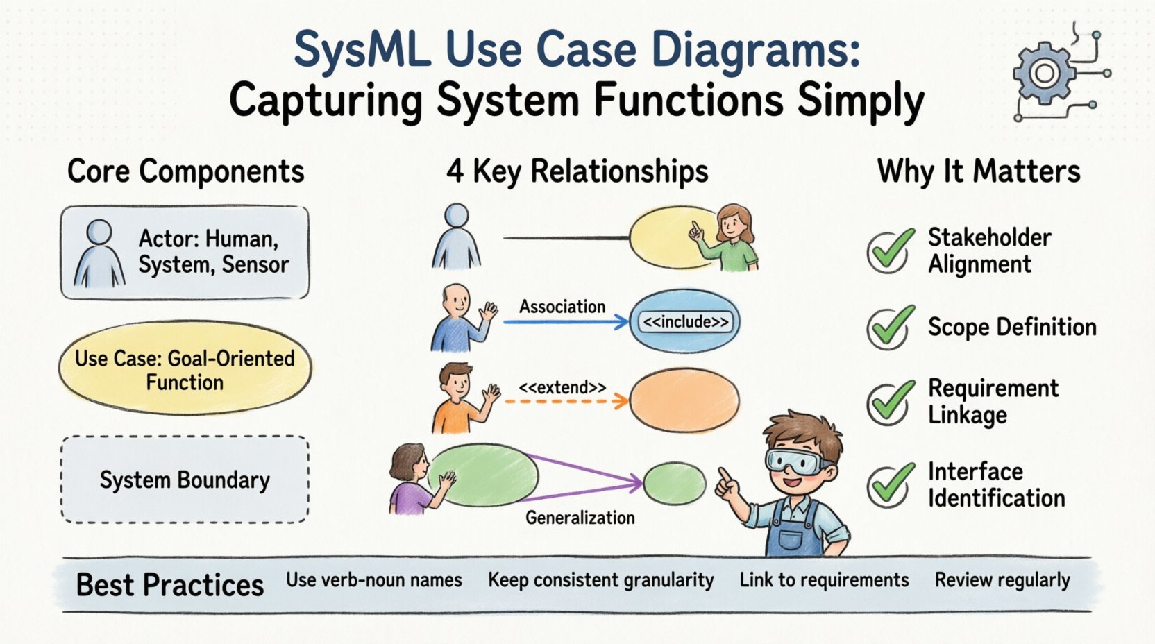
- Stakeholder Alignment: They provide a common language for engineers, project managers, and customers to discuss system goals.
- Scope Definition: They clearly delineate what is inside the system and what is outside.
- Requirement Linkage: They act as anchors for functional requirements, ensuring every requirement has a functional home.
- Interface Identification: They highlight the points of interaction between the system and its environment.
Without a well-defined Use Case Diagram, the system risks scope creep. Functions may be added without understanding their impact on existing boundaries. A diagram acts as a contract for functionality before detailed design begins.
Core Components of a SysML Use Case Diagram 🧱
Building a robust diagram requires understanding the fundamental building blocks. Each element serves a specific purpose in describing the system’s interaction with its environment.
1. Actors 🧑💼
An actor represents a role played by an entity that interacts with the system. Actors are not necessarily humans. They can be:
- External Systems: Another software application or hardware device communicating with the current system.
- Human Operators: The pilot, technician, or administrator managing the system.
- Sensors: Automated inputs that trigger system behavior.
- Regulatory Bodies: Entities that impose constraints or receive reports.
In SysML, actors are often represented as stick figures, though the shape is less important than the semantic meaning. An actor exists outside the system boundary and initiates or participates in a use case.
2. Use Cases 🎯
A use case represents a specific function or service provided by the system. It describes a sequence of actions that yields an observable result of value to an actor. Key characteristics include:
- Goal-Oriented: Each use case has a specific objective, such as “Calibrate Sensor” or “Generate Report”.
- System Boundary: The use case resides inside the system box.
- Traceability: It links back to specific requirements.
It is crucial to distinguish between a Use Case and a Process Step. A process step is a detail within an activity diagram. A use case is a higher-level functional capability.
3. System Boundary 🚧
The system boundary is a rectangle that encloses all use cases. Everything inside is part of the system being modeled. Everything outside is the environment. This boundary is critical for defining responsibilities. If a function is inside the box, the system must perform it. If it is outside, the system interacts with an external entity to achieve it.
Relationships and Interactions 🔗
Connecting actors to use cases and use cases to each other defines the flow of functionality. SysML defines four primary relationship types in this context. Understanding the nuance between them prevents modeling errors.
| Relationship Type | Symbol | Meaning | Example |
|---|---|---|---|
| Association | Line | Direct interaction between actor and use case. | A Technician initiates a Calibration. |
| Include | Arrow + <<include>> | One use case must use another to complete its function. | Login <<include>> Authenticate. |
| Extend | Arrow + <<extend>> | Optional behavior that adds to a base use case. | Emergency Stop extends Normal Operation. |
| Generalization | Triangle | Inheritance of behavior between use cases or actors. | Admin is a type of User. |
Detailed Breakdown of Relationships
Association: This is the most basic link. It shows that an actor participates in a use case. It does not imply direction or control flow, just participation. Multiple associations can exist between the same actor and use case, indicating different roles or interfaces.
Include: This relationship indicates that the included use case is a mandatory part of the base use case. It is used to extract common behavior to avoid duplication. For example, if “Place Order” and “Return Item” both require “Verify Account”, you can define “Verify Account” as an included use case. This keeps the diagram clean and promotes reusability.
Extend: Unlike Include, Extend is optional. It represents a variation or exception. The extending use case adds behavior to the base use case under specific conditions. For instance, a “Download Data” use case might be extended by “Compress Data” only if the file size exceeds a threshold. This captures conditional logic without cluttering the base flow.
Generalization: This allows for hierarchy. An actor generalization means a specialized actor inherits the capabilities of a general actor. A use case generalization means a specific use case inherits the behavior of a broader use case. This is useful for modeling complex user roles or functional hierarchies.
Step-by-Step Modeling Process 🛠️
Creating a diagram is a systematic process. It requires moving from abstract goals to concrete interactions. Follow this logical progression to ensure completeness.
1. Identify Stakeholders and Actors
Begin by listing everyone or everything that interacts with the system. Ask: Who starts the process? Who receives the output? Who provides the input? Avoid modeling specific individuals; model the roles they play. A “Driver” is a role, not “John Smith”.
2. Define the System Boundary
Draw the rectangle. Be conservative. It is better to have a few functions outside the boundary initially than to over-include. If a function is not essential to the core mission of the system, place it outside. This clarifies what the system must do versus what it can do.
3. List Primary Use Cases
Brainstorm the main goals. What is the system for? Write these down as verbs. “Monitor Temperature”, “Adjust Pressure”, “Log Data”. Ensure each has a clear start and end state.
4. Map Interactions
Connect actors to use cases using Association lines. Ensure every actor has a purpose in the system. If an actor is connected to nothing, remove it. If a use case has no actor, question its necessity.
5. Refine with Include/Extend
Look for commonalities. If multiple use cases do the same sub-task, use Include. Look for exceptions. If a task can fail or vary based on conditions, use Extend.
6. Validate Against Requirements
Review the functional requirements list. Does every requirement have a corresponding use case? Does every use case satisfy at least one requirement? This traceability is the backbone of systems engineering.
Common Pitfalls and Anti-Patterns ⚠️
Even experienced engineers can fall into traps when modeling. Recognizing these patterns early saves significant rework later.
- Mixing Phases: Do not mix high-level functional use cases with detailed internal steps. Keep the diagram at the right level of abstraction. If you find yourself listing button clicks, you are too detailed.
- Overusing Extend: Use Extend sparingly. Too many optional flows make the diagram hard to read. Consider moving complex logic to an Activity Diagram.
- Missing Actors: Systems often forget the environment. For example, a “Power Grid” system must interact with a “Grid Manager” actor. If the power source is external, model it as an actor.
- Unclear Boundaries: If a use case depends on a function that is not clearly defined, the boundary is fuzzy. Ensure all internal functions are within the box.
- Verb-Noun Confusion: Use cases should be verbs (“Monitor”, “Control”). If you see nouns (“Monitor”, “Control Unit”), you are likely modeling a block, not a function.
Integration with Other SysML Diagrams 🔗
A Use Case Diagram does not exist in isolation. It is part of a larger model that includes requirements, structure, and behavior. Understanding how it connects to other diagram types is vital for a holistic view.
Requirements Diagrams
The strongest link is between Use Cases and Requirements. Each use case should be associated with one or more functional requirements. This creates a traceability matrix. If a requirement is removed, the use case becomes obsolete. If a use case is removed, the requirement must be re-evaluated.
Activity Diagrams
Use Case Diagrams define what the system does. Activity Diagrams define how it does it. Once a use case is defined, you can drill down into an Activity Diagram to model the control flow, data flow, and decision logic within that specific function. This separation of concerns keeps the model manageable.
Block Definition Diagrams (BDD)
While Use Cases describe functions, Blocks describe structure. A use case often triggers a block operation. For example, the “Fire Engine” use case might invoke a “Pump” block. Mapping these ensures that the physical components exist to support the functional needs.
Best Practices for Clarity and Maintenance 🎯
Maintaining a model over time is as important as creating it. Systems evolve, and the model must evolve with them. Adhere to these guidelines to keep the diagram useful.
- Consistent Naming: Use a standard naming convention. All use cases should start with a verb followed by a noun. For example, “Retrieve Data” instead of “Data Retrieval”.
- Granularity: Keep use cases at a consistent level of granularity. Do not have one use case that takes 5 minutes and another that takes 5 hours. Group them into packages if necessary.
- Documentation: Add descriptions to each use case. A short paragraph explaining the preconditions, postconditions, and main success scenario adds immense value for future readers.
- Version Control: Treat the model as code. Changes should be tracked. If the system scope changes, document why the diagram changed.
- Review Cycles: Schedule regular reviews with stakeholders. A diagram that is never reviewed becomes outdated. Ensure the actors listed are still relevant to the project.
FAQ: Frequently Asked Questions ❓
Q: Can I use SysML Use Case Diagrams for software only?
A: Yes, but they are often too abstract for pure software development. Software teams might prefer User Stories or Sequence Diagrams. SysML shines when hardware, software, and process are all involved.
Q: What is the difference between a Use Case and a Use Case Diagram?
A: A Use Case is a single function or service. A Use Case Diagram is the visual representation of multiple use cases and their relationships within a system context.
Q: How do I handle complex data flows?
A: Use Case Diagrams focus on functionality, not data. For data flow, use Internal Block Diagrams or Sequence Diagrams. Use Case Diagrams show that data is exchanged, not the format or volume.
Q: Is it okay to have no actors?
A: Rarely. A system usually interacts with something. If a system runs autonomously, the environment or a scheduler is the actor. If there are truly no external interactions, the model may be incomplete.
Final Thoughts on Functional Modeling 🌟
SysML Use Case Diagrams are a powerful tool for capturing system functions simply. They strip away technical complexity to reveal the core value of the system. By focusing on actors, boundaries, and functional goals, engineers create a blueprint that guides the entire development lifecycle.
The key to success lies in discipline. Resist the urge to over-model. Keep the diagram focused on the what. Let the how reside in other diagrams. When the Use Case Diagram is clear, the requirements are clear, and the path to implementation is illuminated. This structured approach reduces risk and ensures that the final system meets the needs of the stakeholders.
As systems grow more complex, the need for clear functional modeling increases. SysML provides the standard to meet this need. By adhering to the principles outlined here, teams can build models that are not just documentation, but living maps of system capability.

