
In the complex landscape of systems engineering, understanding how components behave individually is only half the battle. The true complexity lies in how these components interact, exchange information, and coordinate actions over a timeline. SysML Sequence Diagrams provide the visual framework necessary to map these temporal interactions. They are not merely static snapshots but dynamic representations of system behavior that evolve. By utilizing these diagrams, engineers can validate logic, identify bottlenecks, and ensure that the system meets its performance requirements before physical implementation begins.
Tracking interactions across time requires precision. A single message sent at the wrong moment can cascade into system failure. Therefore, mastering the syntax and semantics of SysML sequence modeling is essential for any technical team. This guide explores the mechanics, applications, and best practices for constructing effective sequence diagrams within the Systems Modeling Language.
The Role of Sequence Diagrams in Systems Engineering 📊
Systems engineering involves managing complex projects where hardware, software, and human processes intersect. In this environment, behavior modeling is critical. While Block Definition Diagrams (BDD) show structure, and State Machine Diagrams show states, Sequence Diagrams show process. They answer the question: What happens, and in what order?
- Temporal Context: Unlike static structure diagrams, sequence diagrams introduce the dimension of time. They display events from top to bottom, representing a chronological flow.
- Interaction Focus: The primary focus is on the communication between objects. This includes data exchange, control signals, and status updates.
- Scenario Validation: Engineers use these diagrams to verify specific use cases. They allow for the simulation of scenarios to ensure all edge cases are covered.
- Requirement Traceability: Each interaction can be traced back to a system requirement. This ensures that every function defined in the requirements is implemented and verified in the model.
When modeling a system, the sequence diagram acts as a bridge between abstract requirements and concrete design. It translates the “what” of requirements into the “how” of implementation details.
Anatomy of a SysML Sequence Diagram 🧱
To construct a meaningful diagram, one must understand the constituent elements. SysML inherits much of its syntax from UML but adapts it specifically for systems engineering contexts. Every element serves a distinct purpose in the narrative of system behavior.
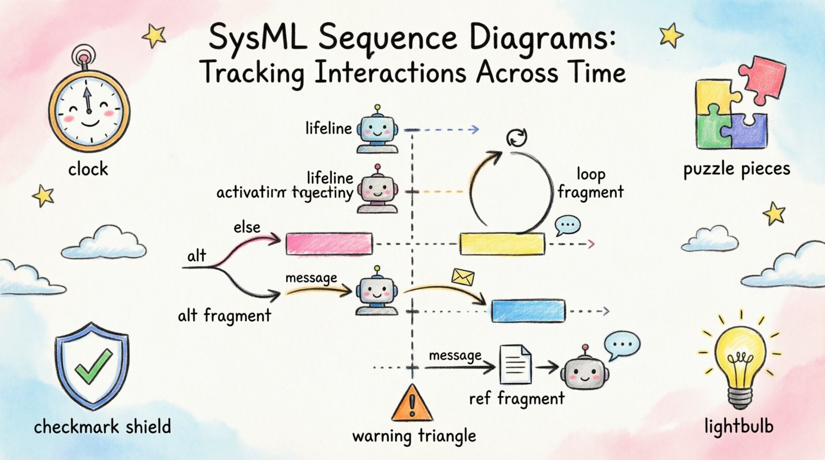
1. Lifelines and Object Instances 🏗️
A lifeline represents a participant in the interaction. It is the vertical dashed line that extends downward from the top of the diagram. Each lifeline corresponds to an object or an instance of a block within the system.
- Instance Specification: A lifeline is often labeled with the instance name and the type of block it represents.
- Scope of Control: The lifeline indicates the duration for which the participant is active in the interaction.
- Multiple Instances: Complex systems may have multiple instances of the same block participating in a single sequence. Each instance gets its own lifeline.
- Deactivation: When a participant is not active, the activation bar disappears, indicating a period of inactivity.
2. Messages and Communication Flows 💬
Messages are the horizontal arrows connecting lifelines. They represent the transfer of control or data. The direction of the arrow indicates the sender and the receiver.
- Synchronous Messages: These require the receiver to complete the action before the sender continues. This is the most common form of interaction.
- Asynchronous Messages: The sender transmits the signal and continues immediately without waiting for a response. This is common in logging or fire-and-forget events.
- Return Messages: Represented by dashed arrows, these indicate the return of control or data to the sender.
- Signal Messages: Used when the interaction is purely a signal without a return value.
3. Activation Bars and Execution Occurrences ⚡
An activation bar (or execution occurrence) is a thin rectangle placed on a lifeline. It indicates that the participant is actively executing an operation during that time interval.
- Duration: The length of the bar corresponds to the time taken to execute the operation.
- Nesting: Nested activation bars show recursive calls or internal processing steps.
- Concurrency: Parallel activation bars on the same lifeline indicate that the object can handle multiple tasks simultaneously.
Key Elements Comparison
| Element | Description | Visual Representation | Use Case |
|---|---|---|---|
| Lifeline | Participant in interaction | Vertical dashed line | Representing objects or blocks |
| Message | Signal or data transfer | Horizontal arrow | Triggering actions or passing data |
| Activation Bar | Period of activity | Rectangle on lifeline | Showing execution time |
| Focus of Control | Control transfer | Small black rectangle | Indicating which object controls the flow |
| Self-Message | Message to self | Curved arrow | Internal processing loops |
Temporal Logic in System Design ⏱️
Time is the defining characteristic of a sequence diagram. It is not just a visual layout; it implies causality. If Event A occurs before Event B, then Event A is a prerequisite for Event B.
Ordering Constraints
The vertical positioning of messages enforces strict ordering rules.
- Strict Ordering: Events higher on the diagram must occur before events lower on the diagram.
- Concurrent Execution: If two lifelines have activation bars at the same vertical level, those processes are running concurrently.
- Parallelism: SysML allows for the modeling of parallel processes using combined fragments, ensuring that time is accounted for correctly across subsystems.
Delays and Timing
Not all systems operate in real-time. Some interactions involve waiting periods. SysML supports the representation of delays.
- Timeouts: Models can represent scenarios where a message is not received within a specific timeframe, triggering an error state.
- Latency: Long activation bars can represent processing delays, helping engineers identify performance bottlenecks.
- Periodic Events: Some interactions occur at regular intervals. These can be modeled using loop fragments to show repetitive behavior.
Interaction Fragments for Logic 🧩
Real-world systems are rarely linear. They involve choices, loops, and optional behaviors. SysML Sequence Diagrams use interaction fragments to encapsulate these logical structures.
1. Alt (Alternative) Fragments
Used to model conditional logic. The diagram splits into different paths based on a guard condition.
- Condition Evaluation: Each path has a condition that must be met for that path to execute.
- Default Path: If no specific condition is met, the default path (if defined) executes.
- Multiple Choices: You can model multiple branches for different outcomes of a decision.
2. Opt (Optional) Fragments
Similar to alternatives, but this indicates that a specific interaction may or may not happen.
- Conditional Execution: If the condition is true, the interaction occurs. If false, the interaction is skipped.
- Use Case: Ideal for optional features or error recovery mechanisms.
3. Loop Fragments
Represents repeated behavior. This is common in data processing or polling mechanisms.
- Iteration Count: You can specify a specific number of iterations.
- While Condition: The loop continues until a condition becomes false.
- For Each: Iterates over a collection of items.
4. Ref (Reference) Fragments
Used to reference another sequence diagram. This helps manage complexity by breaking a large diagram into smaller, manageable pieces.
- Abstraction: Keeps the main diagram clean by hiding detailed logic.
- Reusability: Common sub-processes can be defined once and referenced multiple times.
Integration with Other SysML Diagrams 🔗
Sequence diagrams do not exist in isolation. They are part of a larger ecosystem of models. To ensure consistency, they must align with other diagram types.
Block Definition Diagram (BDD)
The BDD defines the structural hierarchy. The sequence diagram relies on the blocks defined here. Every lifeline in the sequence must correspond to a valid block or part in the BDD.
- Consistency Check: Ensure that all blocks referenced in the sequence exist in the structure diagram.
- Relationships: Verify that associations and dependencies match between the two diagrams.
Internal Block Diagram (IBD)
The IBD details the internal connections of a block. The sequence diagram shows the flow, while the IBD shows the physical or logical ports.
- Port Matching: Messages in the sequence must be routed through the ports defined in the IBD.
- Flow Connections: Ensure that the signal flow aligns with the data flow defined internally.
State Machine Diagram
State machines define the internal states of a block. Sequence diagrams often trigger state transitions.
- Transition Triggers: Messages in the sequence diagram often trigger transitions in a state machine.
- State Validation: Verify that a message is valid for the current state of the object.
Verification and Validation through Sequences ✅
One of the primary benefits of SysML sequence diagrams is the ability to verify system behavior early in the lifecycle. This reduces risk and cost.
- Gap Analysis: Compare the sequence diagram against requirements to ensure no functional gaps exist.
- Interface Verification: Ensure that all interface contracts are met between components.
- Scenario Testing: Use the diagrams to generate test cases. Each path in an Alt fragment can become a specific test scenario.
- Conflict Detection: Identify contradictory behaviors where two components expect different responses to the same input.
Best Practices for Maintainability 🛡️
As systems grow, models can become unwieldy. Following best practices ensures that diagrams remain useful over time.
- Scope Limitation: Keep diagrams focused on specific scenarios. Avoid trying to model the entire system in one diagram.
- Abstraction Levels: Use different levels of detail. High-level diagrams show major milestones; detailed diagrams show specific data exchanges.
- Naming Conventions: Use consistent naming for blocks, messages, and lifelines. This aids in traceability.
- Version Control: Treat diagrams as code. Manage changes and versions to track evolution.
- Documentation: Add comments to complex logic. Explain the “why” behind certain flows, not just the “what”.
Common Modeling Errors to Avoid ⚠️
Even experienced engineers can fall into traps when modeling behavior. Being aware of common pitfalls helps maintain model integrity.
| Error | Impact | Mitigation Strategy |
|---|---|---|
| Circular Dependencies | Deadlocks in logic | Check for feedback loops that lack termination conditions |
| Mixed Abstraction Levels | Confusion for readers | Keep message granularity consistent within a diagram |
| Missing Return Messages | Incomplete flow | Ensure every synchronous message has a return path |
| Over-Complexity | Unmaintainable model | Refactor into smaller diagrams using Ref fragments |
| Ignoring Timeouts | System hangs | Include error handling paths for delayed messages |
Advanced Patterns for Complex Systems 🚀
For highly complex systems, standard patterns may not suffice. Advanced modeling techniques can address specific challenges.
1. Parallel Processing
When multiple subsystems operate simultaneously, use parallel combined fragments. This explicitly models concurrency and helps identify race conditions.
- Synchronization: Ensure that parallel branches converge correctly.
- Resource Sharing: Be careful when multiple threads access shared resources.
2. Event-Driven Architectures
Modern systems often rely on events rather than direct calls. Use signal messages to model event-driven interactions.
- Pub/Sub Models: Represent publishers and subscribers clearly.
- Event Queues: Model the delay between event generation and processing.
3. Hierarchical Sequencing
Break down complex sequences into sub-sequences. This modular approach allows teams to work on different parts of the system simultaneously.
- Traceability: Maintain links between the parent sequence and child sequences.
- Encapsulation: Hide internal details of sub-processes until they are needed.
Ensuring Consistency Across the Model 🔄
Maintaining consistency across the entire model is a continuous effort. Inconsistencies lead to errors in the final system.
- Automated Checks: Use model checking tools to identify inconsistencies between diagram types.
- Regular Reviews: Conduct peer reviews of sequence diagrams to catch logic errors.
- Requirement Updates: When requirements change, update the diagrams immediately to avoid drift.
- Baseline Management: Establish baselines for stable models to track changes over time.
Summary of Key Takeaways 📝
SysML Sequence Diagrams are a fundamental tool for tracking interactions across time. They provide a clear, visual representation of system behavior that is essential for validation and verification. By understanding the core elements, utilizing interaction fragments, and maintaining consistency with other diagram types, engineers can create robust models.
- Focus on Time: Always consider the temporal aspect of every interaction.
- Validate Logic: Use fragments to handle complex decision-making and loops.
- Integrate Models: Ensure alignment with structure and state diagrams.
- Keep it Clean: Follow best practices to maintain model readability.
- Iterate: Treat diagrams as living documents that evolve with the system.
Through disciplined modeling, the sequence diagram becomes more than just a picture. It becomes a specification of behavior that guides the development process from concept to reality.
