In the complex landscape of systems engineering, clarity is the most valuable asset. When development teams move from abstract needs to concrete designs, the risk of misalignment grows. This is where the SysML Requirements Diagram becomes indispensable. It serves as the foundational bridge connecting what a system must do to how the system is built. Without this link, verification becomes a guessing game, and validation loses its target.
This guide explores the mechanics of modeling requirements in SysML. We will examine how to structure these diagrams to support traceability, reduce ambiguity, and ensure every line of design code or hardware component can be traced back to a stakeholder need. By mastering the relationships within this diagram type, engineers can manage change more effectively and maintain integrity throughout the project lifecycle.
Understanding the Requirements Diagram Structure 📄
The Requirements Diagram is distinct within the SysML suite because it focuses almost exclusively on the definition and interconnection of requirements. Unlike other diagrams that visualize behavior or structure, this diagram acts as a repository for the textual and logical constraints of the system. It is the single source of truth for what the system is required to achieve.
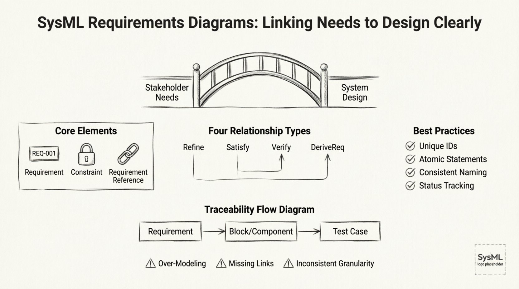
To build an effective model, one must understand the core elements involved:
- Requirement: The fundamental unit of work. A requirement defines a condition or capability that a system, system element, or process must satisfy. It is typically defined by a unique identifier, a text description, and often a status.
- Constraint: A rule that limits the design space. Constraints are often mathematical or logical conditions that must hold true for the system to function correctly.
- Requirement Reference: A link that connects two requirements. This establishes a hierarchy or a dependency between different levels of need.
Organizing these elements requires discipline. A flat list of requirements is difficult to navigate and manage. Instead, a hierarchical structure should be established. This allows engineers to drill down from high-level stakeholder needs to detailed engineering specifications. This structure supports impact analysis. When a high-level need changes, the model shows which lower-level requirements are affected.
Core Relationships in SysML 🔗
The true power of the SysML Requirements Diagram lies in the relationships between elements. These links define the logical flow of information and responsibility. There are four primary types of relationships used to connect requirements to other system elements. Understanding the semantics of each is critical for accurate modeling.
The table below outlines the specific use cases for each relationship type:
| Relationship Type | Direction | Meaning | Common Use Case |
|---|---|---|---|
| Refine | Source to Target | The source provides more detail or a more specific implementation of the target. | Linking a high-level need to a detailed engineering specification. |
| Satisfy | Target to Source | The target element provides a solution that fulfills the requirement. | Linking a specific hardware component or software function to the requirement it meets. |
| Verify | Target to Source | The target provides a means to test or confirm the requirement. | Linking a test case or inspection method to the requirement being tested. |
| DeriveReq | Source to Target | The target requirement is derived from the source requirement. | Creating a sub-requirement that must be true if the parent requirement is true. |
Using these relationships correctly prevents confusion during audits or reviews. For example, using Satisfy incorrectly can lead to a situation where a component is linked to a requirement but does not actually fulfill it. The direction of the arrow matters. In SysML, the arrow points from the element providing the value to the element receiving the value. For Satisfy, the arrow points from the component to the requirement. For Verify, the arrow points from the test to the requirement.
Structuring Requirements for Clarity 🏗️
Once the relationships are understood, the next step is structuring the content. A cluttered diagram with tangled lines obscures the system architecture rather than revealing it. To maintain readability, follow these structural guidelines:
- Unique Identifiers: Every requirement must have a unique ID. This facilitates tracking across different documents and tools. Avoid generic names like “Requirement 1”.
- Atomic Statements: A requirement should express a single condition. Combining multiple conditions into one statement makes it difficult to verify and trace. If a statement requires two separate tests, it should be split into two requirements.
- Consistent Naming: Use a consistent naming convention for all requirements. This might include a prefix indicating the domain, such as “REQ-SD” for Software Design or “REQ-HW” for Hardware.
- Status Tracking: Clearly mark the status of each requirement. Common statuses include Proposed, Approved, Implemented, and Verified. This provides a quick visual overview of project health.
Visual grouping is also essential. If the diagram becomes too large, use partitions or frames to separate different subsystems. This helps the reader focus on specific areas of the system without getting lost in the global view. Grouping by subsystem aligns the requirements model with the physical architecture of the system.
Integrating with System Architecture 🔗
A Requirements Diagram should not exist in isolation. It must interact with other SysML diagrams to create a cohesive model. The Block Definition Diagram (BDD) and the Internal Block Diagram (IBD) are the primary partners in this ecosystem.
When linking requirements to the BDD, you establish which blocks satisfy which needs. This creates a clear path from text to structure. For instance, a requirement stating “The system shall weigh less than 50kg” should be satisfied by a block representing the chassis or the material selection. This link allows engineers to perform weight analysis directly against the requirement.
Similarly, linking to the IBD helps define internal interfaces. If a requirement specifies data flow between two modules, the IBD can show the ports and connectors that facilitate this flow. The connection between the requirement and the interface ensures that the physical design supports the functional need.
Consider the following integration points:
- Blocks: Link requirements to the specific blocks that implement the functionality.
- Interfaces: Link interface requirements to the interface definitions in the BDD.
- Operations: Link behavioral requirements to the operations defined in activity diagrams.
This integration creates a web of traceability. If a design change occurs in a block, the system can identify which requirements are impacted. This prevents “silent failures” where a design change violates an unlinked requirement.
Verification and Validation Processes ✅
The ultimate goal of modeling requirements is to ensure the final product meets the intended purpose. Verification asks, “Did we build the product right?” Validation asks, “Did we build the right product?” The Requirements Diagram supports both.
For verification, the Verify relationship is key. Each requirement should have at least one associated verification method. This could be an analysis, an inspection, a demonstration, or a test. By linking these methods directly to the requirement in the diagram, the engineering team can ensure that no requirement is left untested.
Traceability matrices are often generated from these models. A traceability matrix is a report that lists every requirement and its corresponding design element and test case. This document is critical for certification and compliance. Regulatory bodies often require proof that every requirement has been addressed. A well-maintained SysML model makes generating this matrix a matter of querying the data rather than manually compiling spreadsheets.
Validation is supported by ensuring the requirements themselves are complete and consistent. The diagram helps identify gaps. If a functional block has no incoming requirements, it may be unnecessary. If a requirement has no outgoing Satisfy link, it is not being implemented. These gaps become visible early in the design phase.
Common Pitfalls to Avoid ⚠️
Even with a clear methodology, modeling efforts can go astray. Recognizing common mistakes helps engineers maintain a robust model. Below are frequent issues encountered in systems engineering projects.
- Over-Modeling: Trying to model every single detail can lead to a diagram that is too complex to manage. Focus on the critical requirements that drive design decisions. Minor implementation details can be documented in text files rather than the model.
- Missing Links: Creating requirements without linking them to anything is useless. An orphaned requirement does not contribute to the design or verification process. Every requirement must be either satisfied or verified.
- Inconsistent Granularity: Mixing high-level needs with low-level implementation details in the same cluster creates confusion. Keep the hierarchy clear. High-level needs should be at the top, with detailed specs below.
- Ignoring Change: Requirements change. If the model is not updated when a requirement is modified, the traceability chain breaks. Establish a change management process that requires updating the model alongside the requirements document.
- Tool Dependency: Do not rely on specific tool features to enforce logic. The model should make sense even if exported to a different format. Focus on the underlying logic of the relationships, not just the visual appearance.
Managing Change and Impact Analysis 🔄
One of the most significant advantages of a structured SysML model is the ability to manage change. In any long-term project, requirements will evolve. Stakeholders may request new features, or constraints may shift due to external factors. Without a model, assessing the impact of these changes is difficult.
With a properly linked diagram, impact analysis becomes systematic. When a requirement is modified, the model reveals all downstream elements. This includes:
- Design Elements: Which blocks or components must be redesigned?
- Other Requirements: Are there dependent requirements that must also change?
- Verification Assets: Which test cases need to be updated or rewritten?
This visibility reduces risk. Engineers can estimate the cost and effort of a change before committing to it. It also prevents scope creep. If a change is requested, the team can see exactly what is involved and decide if it is worth the investment.
Furthermore, maintaining this model requires discipline. It is not a one-time setup. It is a living artifact that evolves with the system. Regular reviews should be conducted to ensure links are still valid. As components are replaced or architectures shift, the diagram must be updated to reflect the new reality.
Conclusion: The Value of Clear Linking 🎯
Building a system is a complex endeavor that requires precision. The SysML Requirements Diagram provides the structure needed to maintain that precision. By clearly linking needs to design, engineers create a transparent environment where decisions are traceable and verifiable.
The effort invested in modeling these relationships pays dividends in reduced rework, clearer communication, and higher confidence in the final product. It transforms requirements from static text into active components of the system architecture. When every requirement is linked, verified, and satisfied, the path from concept to reality becomes a straight line rather than a series of blind guesses.
Adopting these practices ensures that the system meets its intended purpose. It allows teams to focus on solving engineering challenges rather than hunting for missing links. In the end, a well-constructed Requirements Diagram is not just a document; it is a roadmap for successful system delivery.