
When modeling complex systems using SysML, the Internal Block Diagram (IBD) serves as the blueprint for how system parts interact. It is where the architecture comes alive, moving from abstract requirements to concrete connections. At the heart of this interaction lies the component interface. Defining these interfaces correctly ensures that every part of the system speaks the same language, communicates effectively, and behaves predictably.
This guide explores the mechanics of defining component interfaces within SysML Internal Block Diagrams. We will examine ports, properties, connectors, and the semantic rules that govern data flow. By mastering these structural elements, engineers can build models that are robust, maintainable, and ready for analysis.
🧩 Understanding the Internal Block Diagram
An Internal Block Diagram provides a structural view of a block. It shows the internal composition of a block and the interactions between its parts. Unlike the Block Definition Diagram (BDD), which defines the types of blocks, the IBD defines instances and their relationships.
Key elements found in an IBD include:
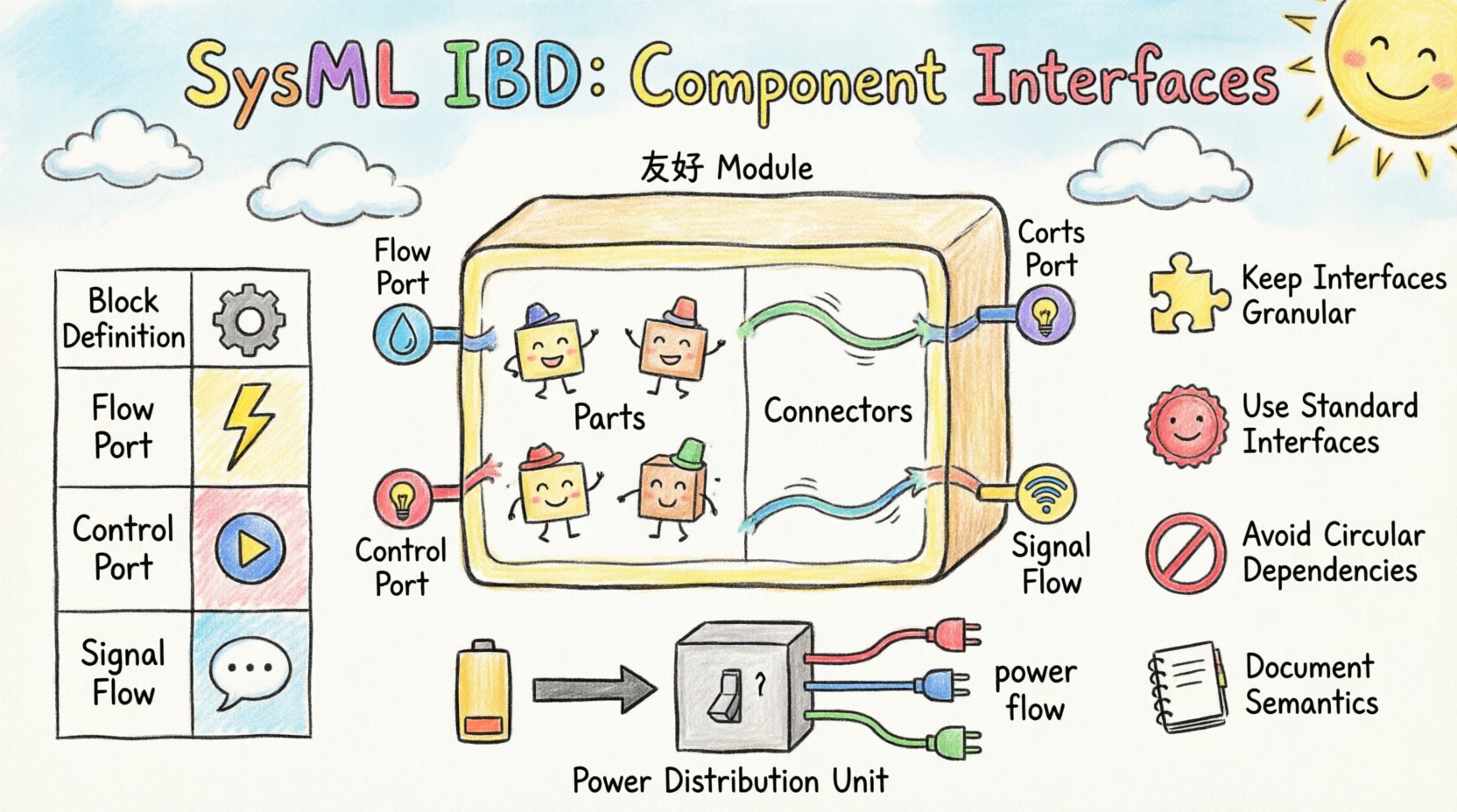
- Parts: Instances of blocks that make up the composite block.
- Connectors: Links that define how parts are wired together.
- Ports: Points of interaction where parts connect to the outside world or to each other.
- Properties: Attributes of the block that are not necessarily points of interaction.
The goal of the IBD is to visualize the flow of information and material within the system. To do this effectively, the interfaces at the boundaries of parts must be clearly defined. An undefined interface is like a loose wire; it creates ambiguity and potential failure points in the system design.
🔌 The Anatomy of a Component Interface
An interface in SysML is a collection of requirements for behavior. When applied to a block, it specifies what the block must provide or require to function correctly. In the context of an IBD, interfaces are typically realized through ports.
🚦 Ports vs. Properties
One of the most common distinctions in SysML modeling is between ports and properties. Both represent interactions, but they serve different purposes.
- Ports: Represent a point of interaction. A port has a type, which is often an interface. It defines the contract for communication. Ports can be used for control, flow, or signal exchange.
- Properties: Represent a physical or logical attribute of the block. Properties can be accessed, but they do not inherently define an interaction contract unless they are typed as an interface.
When defining a component interface, you must decide if the connection is a functional interaction (port) or a structural attribute (property). For example, a fuel tank might have a fuel level property, but it will have a port for fuel flow.
📊 Interface Types in SysML
Different types of interfaces handle different kinds of data. Using the correct type ensures that the system model accurately reflects physical reality.
| Interface Type | Primary Use Case | Example |
|---|---|---|
| Block Definition | Structural connections | A mechanical bracket |
| Flow Port | Physical material or energy flow | Electrical current, hydraulic fluid |
| Control Port | Logic or command signals | Start/Stop command, Sensor trigger |
| Signal Flow | Data exchange without flow direction | Telemetry data, Status updates |
Choosing the right interface type is critical for downstream analysis. If you model a power connection as a control port, simulation tools may fail to calculate energy consumption correctly.
🔗 Defining Interfaces on Ports
Once you have selected an interface type, you must apply it to the port. This process is known as typing a port. The interface becomes the contract that the port must satisfy.
When defining the interface, consider the following steps:
- Define the Interface Definition: Create a block that represents the interface. This block should contain the operations or flows that the interface supports.
- Assign the Type: Select the port in the IBD and assign the interface block as its type.
- Specify Direction: Determine if the port is a flow port or a control port.
- Document Usage: Add documentation to explain the purpose of the interface. This helps future engineers understand the constraints.
A well-typed port acts as a barrier. It prevents incompatible connections from being made. If a port requires a specific signal type, the modeler cannot accidentally connect a different signal type without violating the model integrity.
🧪 Connectors and Binding
Interfaces are useless without connections. Connectors bind ports together, allowing data or material to flow between parts. The binding process relies heavily on the interfaces defined earlier.
🔗 Connector Types
There are two main ways to connect parts in an IBD:
- Reference Connector: Connects two ports. This is used for control signals and standard interactions.
- Flow Connector: Connects two flow ports. This is used for physical flows like electricity or fluids.
When a connector is created, SysML checks the types of the ports involved. If the ports are typed with interfaces, the system checks for compatibility. This is known as interface conformance.
🔗 Binding Specifications
Sometimes, a connector needs to do more than just link two ports. A binding specification can define how the data is transformed or routed. This is useful in complex systems where data might need conversion before it reaches the destination.
For example, a sensor might output an analog voltage, but the controller expects a digital signal. A binding specification on the connector can model this conversion logic, ensuring the model reflects the hardware reality.
🏗️ Best Practices for Interface Definition
To maintain a clean and scalable model, follow these best practices when defining component interfaces.
🏗️ 1. Keep Interfaces Granular
Do not create a single massive interface for everything. Break down interfaces into smaller, focused units. A single block should not have one giant port for all its interactions. Instead, use multiple ports for distinct functions like power, data, and control.
- Why: Granular interfaces make the model easier to read and modify.
- Why: It allows for independent testing of different subsystems.
🏗️ 2. Use Standard Interfaces
If your organization uses standard interfaces for common components, reuse them. Define a standard “Power Supply” interface and apply it to all power sources in the system. This reduces redundancy and ensures consistency.
- Benefit: Consistency across the model.
- Benefit: Easier onboarding for new engineers.
🏗️ 3. Avoid Circular Dependencies
Be careful when defining interfaces that depend on each other. If Interface A requires Interface B, and Interface B requires Interface A, you create a circular dependency. This can make the model difficult to parse and simulate.
- Rule: Define interfaces hierarchically. Lower-level interfaces should not depend on higher-level ones.
🏗️ 4. Document the Semantics
Names are good, but semantics are better. An interface named “Data” is vague. An interface named “TelemetryStream” is specific. Document the data format, frequency, and units within the interface definition.
- Example: “Voltage: 0-5V DC, 100Hz sampling rate.”
⚠️ Common Pitfalls in Interface Modeling
Even experienced modelers can make mistakes when working with interfaces. Being aware of these common pitfalls helps you avoid them.
⚠️ 1. Mixing Flow and Control
Do not mix flow ports and control ports on the same connector. A flow port implies physical movement of matter or energy. A control port implies logical signaling. Connecting them creates a semantic error in the model.
⚠️ 2. Overusing Properties
Using properties instead of ports for interactions is a common error. Properties are for internal state, not for external interaction. If a part needs to send a signal to another part, use a port, not a property.
⚠️ 3. Ignoring Interface Inheritance
SysML supports interface inheritance. If Interface A extends Interface B, a block typed with Interface A satisfies the requirements of Interface B. Ignoring this can lead to redundant definitions. Use inheritance to create a hierarchy of interfaces.
⚠️ 4. Forgetting Directionality
Flow ports have directionality. Data flows from source to destination. Control ports can be bidirectional. Ensure the directionality matches the physical system. A sensor should not have a flow port that sends power back to the grid.
🔄 Integrating with Other Diagrams
Interfaces defined in the IBD do not exist in isolation. They must align with definitions in other diagrams to ensure model coherence.
🔄 Block Definition Diagrams (BDD)
The BDD defines the block types. The IBD uses these types. If you define a port in the IBD, the interface it uses should be defined in the BDD. This separation of concerns keeps the model organized.
🔄 State Machine Diagrams
State machines often define the behavior of a block. The triggers for state transitions often come from ports. Ensure that the interface types used in the state machine match the port types in the IBD.
🔄 Requirement Diagrams
Requirements often specify interface constraints. For example, a requirement might state “The system must support 5G connectivity.” This requirement should be linked to the specific interface defined in the IBD. This traceability ensures that the design meets the requirements.
📈 Scalability and Maintenance
As systems grow, the number of interfaces increases. Managing this complexity is key to long-term success.
- Modular Design: Group interfaces by function. Create subsystem blocks that encapsulate complex interface logic.
- Version Control: Keep track of interface changes. If an interface changes, know which parts of the system are affected.
- Review Cycles: Regularly review the IBDs to ensure interfaces are still relevant. Remove obsolete interfaces to keep the model clean.
🎯 Summary of Key Concepts
To recap, defining component interfaces in SysML Internal Block Diagrams involves several critical steps:
- Identify Interactions: Determine where data, energy, or control signals enter or leave a block.
- Select Interface Type: Choose between flow, control, or signal interfaces based on the nature of the interaction.
- Define Ports: Create ports and assign the interface types to them.
- Connect Components: Use connectors to link ports, ensuring type compatibility.
- Validate: Check the model for consistency across BDDs, SMDs, and requirement diagrams.
By adhering to these principles, you create a system model that is not just a drawing, but a precise specification of the engineering reality. The effort invested in defining interfaces correctly pays off during simulation, testing, and implementation phases.
🔍 Deep Dive: Interface Semantics
Understanding the semantics of an interface goes beyond syntax. It involves understanding the behavior the interface enforces.
- Behavioral Contracts: An interface defines what a part must do. It is a contract. If a part implements an interface, it guarantees certain behaviors.
- Operational Constraints: Interfaces can constrain the range of values. For example, a voltage interface might constrain the value to 0-5V.
- Temporal Constraints: Interfaces can specify timing. A control signal might need to pulse every 10 milliseconds.
These semantic details are often captured in the interface definition block. They can be linked to analysis models to verify that the design meets performance criteria.
🛠️ Practical Example: A Power Distribution Unit
Let us consider a Power Distribution Unit (PDU). The PDI receives power from a source and distributes it to loads.
- Input Port: A flow port typed with “PowerInput” interface.
- Output Ports: Multiple flow ports typed with “PowerOutput” interface.
- Control Port: A control port typed with “SwitchCommand” interface.
- Connector: Connects the Input port to the internal bus.
- Connector: Connects the internal bus to the Output ports.
This structure clearly defines how power flows and how control signals operate. It separates the physical power flow from the logical switching commands. This separation makes the model easier to analyze for power losses or control latency.
🔮 Future Considerations
As systems become more complex, the role of interfaces will grow. Model-Based Systems Engineering (MBSE) relies heavily on precise interface definitions. Future tools may automate interface checking, ensuring that all constraints are met before physical implementation begins.
Staying current with SysML standards is essential. New profiles and extensions are introduced regularly to support specific domains like automotive or aerospace. Understanding the core interface concepts allows you to adapt to these new standards quickly.
📝 Final Thoughts
Defining component interfaces is a foundational skill in SysML modeling. It transforms abstract requirements into concrete architectural decisions. By focusing on clarity, consistency, and correctness, you ensure that your models serve their purpose effectively.
Remember that a model is a living document. As requirements evolve, interfaces may need to change. Regular maintenance and review are necessary to keep the model accurate. With a solid understanding of ports, properties, and connectors, you are well-equipped to tackle complex system designs.
Invest time in getting the interfaces right. The downstream benefits in simulation, verification, and production are substantial. A well-defined interface is the bridge between design and reality.

