Modern engineering challenges involve intricate networks of hardware, software, and human interactions. Managing this complexity without a structured approach often leads to ambiguity, rework, and cost overruns. Systems Modeling Language (SysML) provides a standardized method to represent these systems visually and logically. Among its capabilities, structural views stand out as the foundation for defining what a system is before determining what it does.
This guide explores how to leverage SysML structural views to bring clarity to complex architectures. We will examine the core diagrams, relationship types, and modeling strategies that help engineers communicate system boundaries and interactions effectively.
Understanding Structural Views in SysML 🧩
Systems engineering relies on models to capture requirements, behavior, and structure. While behavioral diagrams describe actions and flows, structural views focus on composition and organization. They answer critical questions:
- What components make up the system?
- How are these components connected?
- What interfaces exist between parts?
- How does the system decompose into subsystems?
Structural modeling creates a static snapshot of the system architecture. This snapshot serves as the backbone for other modeling activities. Without a solid structural definition, behavioral specifications can become disconnected from physical reality.
There are two primary diagrams used for structural modeling:
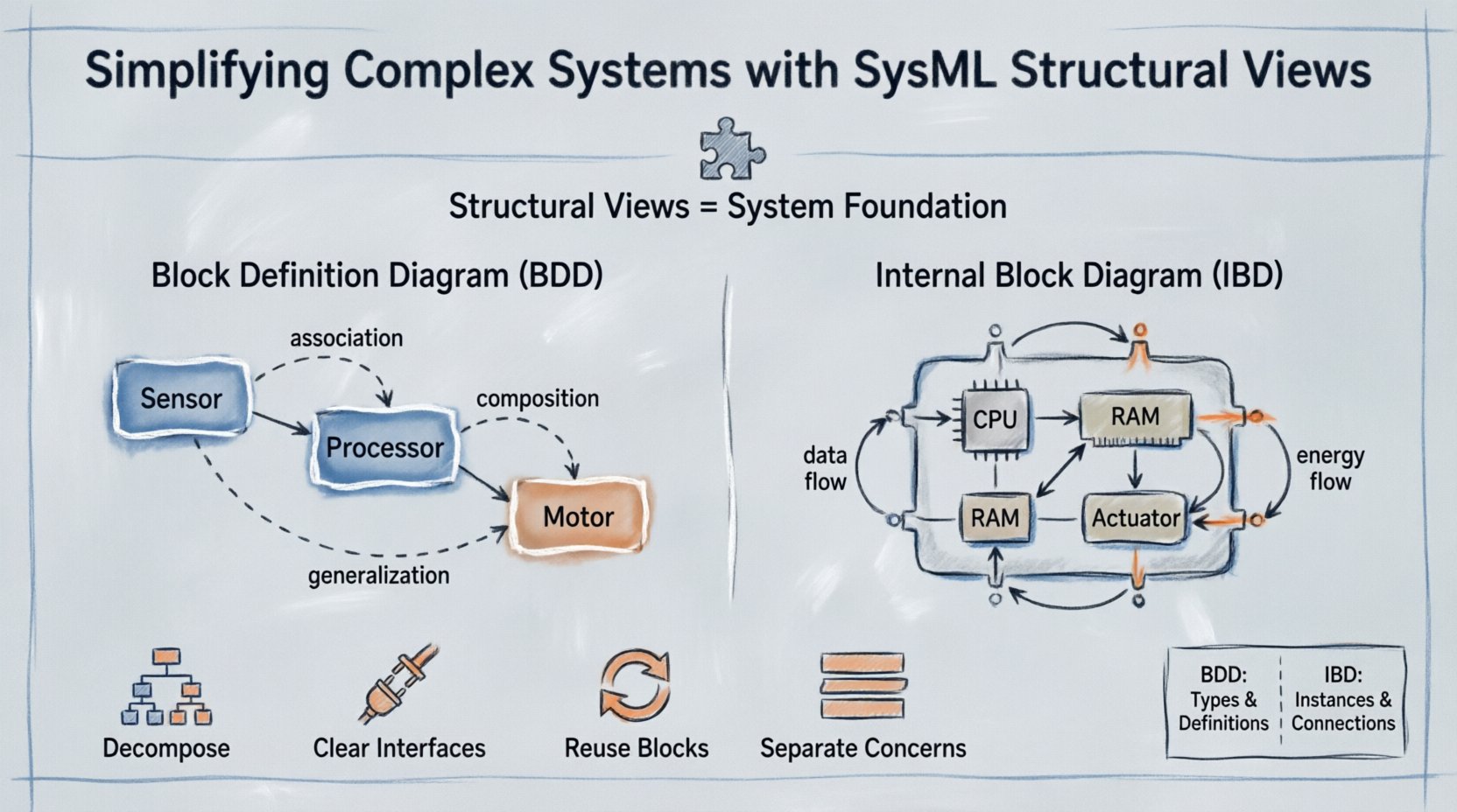
- Block Definition Diagram (BDD): Focuses on the definitions of blocks and their relationships in a general context.
- Internal Block Diagram (IBD): Focuses on the internal composition of a block, showing how parts connect within a specific context.
The Block Definition Diagram (BDD) 📐
The BDD is the starting point for structural modeling. It defines the building blocks of the system. Think of it as the blueprint for the system’s vocabulary. Every element in the system must be defined as a block, or a type of block, within the BDD.
Core Elements of a BDD
When constructing a BDD, you work with specific elements that define the system’s taxonomy:
- Blocks: The fundamental unit of structure. A block represents a physical or logical component, such as a sensor, a processor, or a software module.
- Value Types: Represent data types or parameters, such as voltage, temperature, or string identifiers.
- Enumerations: Define a set of named values for a property.
Relationships in the BDD
Blocks rarely exist in isolation. They relate to one another through specific associations. Understanding these relationships is crucial for accurate modeling.
- Association: A structural link between two blocks. It implies a usage relationship without ownership. For example, a Driver block might be associated with a Car block.
- Aggregation: A specific type of association representing a whole-part relationship where the part can exist independently of the whole. If the system is removed, the part still exists.
- Composition: A strong form of aggregation. The part cannot exist without the whole. If the system is destroyed, the part is destroyed.
- Generalization: Represents inheritance or specialization. A Electric Motor block might be a specialization of a generic Motor block.
- Dependency: Indicates that one block relies on another. Changes to the supplier may affect the client.
- Refinement: Used to link a specification to an implementation. It connects an abstract requirement to a concrete block.
The Internal Block Diagram (IBD) 🔌
Once the blocks are defined in the BDD, the IBD dives deeper into how those blocks interact internally. It details the flow of data and energy within a specific composite block.
Key Components of an IBD
The IBD uses a slightly different set of symbols to represent internal connectivity:
- Parts: Instances of blocks defined elsewhere. A part represents a specific occurrence of a block within a composite.
- Properties: Attributes of a block that do not represent composition. These are often data values or parameters.
- Ports: Interaction points where the block connects to the outside world. Ports define the interface for communication.
- Connectors: Lines that link ports to parts or other ports. They define the flow of information or material.
Port Types
Ports are not just connection points; they define the contract of interaction. SysML distinguishes between:
- Flow Ports: Allow the flow of information or physical quantities (e.g., data, power, fluid).
- Operation Ports: Allow the invocation of operations or services.
- Reference Ports: Used to connect to external interfaces or services without ownership.
BDD vs. IBD: A Comparison 📊
Confusion often arises between when to use a BDD and when to use an IBD. The following table clarifies the distinctions to ensure proper application of the modeling language.
| Feature | Block Definition Diagram (BDD) | Internal Block Diagram (IBD) |
|---|---|---|
| Focus | Types and definitions of blocks. | Instances and internal connections. |
| Primary Elements | Blocks, Value Types, Relationships. | Parts, Properties, Ports, Connectors. |
| Scope | System-wide or subsystem definitions. | Specific composite block context. |
| Relationships | Association, Aggregation, Generalization. | Connectors, Flow Specifications. |
| Analogy | Class Diagram in Object-Oriented Design. | Component Diagram or Circuit Diagram. |
Strategies for Simplifying Complexity 🧠
Creating models can inadvertently add complexity if not managed well. The goal is simplification, not documentation for documentation’s sake. Here are strategies to maintain clarity.
1. Hierarchical Decomposition
Do not attempt to model the entire system on a single diagram. Use hierarchy to manage scope.
- Start with a top-level system block.
- Decompose this block into major subsystems.
- Move to detailed diagrams for specific subsystems.
- Ensure traceability between levels using refinement relationships.
2. Define Clear Interfaces
Interfaces act as the contract between components. A well-defined interface reduces dependency coupling.
- Use ports to define inputs and outputs.
- Specify flow specifications for data types.
- Document the expected behavior of the interface in requirements.
3. Reuse Existing Blocks
Standardizing components reduces errors and speeds up development.
- Identify common subsystems across different projects.
- Create generic blocks for these commonalities.
- Apply specialization (generalization) to create variants.
4. Separate Concerns
Keep structural details separate from behavioral details initially.
- Define the structure first.
- Analyze the behavior using activity or state machine diagrams later.
- Link behavior to specific ports or parts in the structure.
Common Modeling Challenges ⚠️
Even experienced modelers face hurdles. Recognizing these issues early prevents structural debt.
Over-Modeling
It is tempting to model every possible attribute and relationship. This leads to diagrams that are too dense to read.
- Solution: Focus on the scope of the current engineering phase. If a detail is not needed for the next decision, leave it out.
Missing Connectors
In IBDs, forgetting to connect a port to a part results in a broken model.
- Solution: Perform regular consistency checks. Ensure every flow port is connected to a compatible connector.
Unclear Ownership
Distinguishing between aggregation and composition can be difficult.
- Solution: Ask: “If the parent is removed, does the child survive?” If yes, use aggregation. If no, use composition.
Ignoring Value Types
Structural models often lack data definition, leading to ambiguity in interfaces.
- Solution: Define value types for all parameters. Specify units and ranges to ensure physical consistency.
Integration with Requirements and Behavior 🔄
Structural views do not exist in a vacuum. They must integrate with the rest of the systems engineering lifecycle.
Linking to Requirements
Every block should trace back to a requirement. This ensures that the structure is built to satisfy needs.
- Use the Refine relationship to link a block to a requirement.
- Use the Satisfy relationship to show how a block fulfills a requirement.
Linking to Behavior
Behavioral diagrams describe what the system does. Structural diagrams describe where the behavior happens.
- Connect activity diagrams to the parts or ports that execute the actions.
- Ensure the structural ports match the flow specifications in the activity diagram.
- This alignment validates that the architecture can support the intended functionality.
Best Practices for Collaboration 👥
Models are communication tools. They bridge the gap between stakeholders, including hardware engineers, software developers, and management.
Consistent Naming Conventions
- Use a standardized naming scheme for all blocks and ports.
- Prefix subsystems with their domain (e.g., HW-Sensor, SW-Control).
- Avoid abbreviations that are not universally understood.
Visual Hierarchy
- Group related blocks together visually.
- Use frames to delineate different subsystems within a diagram.
- Keep labels readable and concise.
Version Control
- Track changes to the structural model over time.
- Document the rationale for structural changes.
- Ensure all team members are working from the latest model revision.
Validating the Structural Model ✅
Before releasing a model for implementation, validation is necessary.
- Completeness: Are all required blocks defined?
- Connectivity: Are all necessary paths established?
- Feasibility: Do the interfaces match the available technology?
- Consistency: Do the BDD and IBD definitions align?
Validation ensures that the model is not just a drawing, but a usable specification. Automated tools can assist in checking for disconnected ports or undefined types, but human review remains essential for architectural soundness.
Looking Ahead: System Evolution 🚀
Systems change. Requirements evolve, and technologies advance. A robust structural model accommodates these changes.
- Modularity: Design blocks to be easily swapped or upgraded.
- Scalability: Ensure the structure can support future expansion.
- Traceability: Maintain links from the structure to the requirements throughout the lifecycle.
By treating the structural model as a living artifact, organizations can reduce the cost of change. Modifications in the model reflect immediately in the design intent, preventing costly errors during physical implementation.
Summary 📝
SysML structural views provide a disciplined approach to defining system architecture. By separating definitions (BDD) from internal composition (IBD), engineers can manage complexity effectively. Proper use of blocks, ports, and connectors creates a clear map of the system landscape.
Success in structural modeling relies on disciplined decomposition, clear interfaces, and consistent collaboration. When these elements are in place, the structural model becomes a powerful asset for decision-making, risk reduction, and system validation.
Adopting these practices ensures that complex systems remain understandable and manageable throughout their development lifecycle.