Systems Modeling Language (SysML) provides a robust framework for defining complex systems. However, navigating the nuances of modeling without a structured approach can lead to inconsistent diagrams and inefficient workflows. For junior systems engineers, establishing a foundation of reusable patterns is essential. These patterns serve as standardized building blocks that ensure clarity, maintainability, and interoperability across projects. This guide outlines the core patterns required for effective SysML modeling, focusing on structure, behavior, and requirements without relying on specific tooling vendors.
📐 Why Standardization Matters in SysML
Consistency in modeling is not just about aesthetics; it is about communication. When multiple engineers work on the same system model, discrepancies in notation or structure can cause significant misunderstandings. Reusable patterns address this by providing a common vocabulary for system architecture.
Reduced Cognitive Load: Engineers can focus on the system logic rather than the diagram layout.
Faster Onboarding: New team members understand the model structure immediately.
Improved Traceability: Standardized connections ensure requirements map correctly to design elements.
Automated Analysis: Consistent structures allow tools to run checks and validation rules more effectively.
Patterns should be treated as templates. They define how elements are named, grouped, and connected. By adopting these patterns, teams create a predictable environment where the model speaks a single language.
🧱 Structural Modeling Patterns
Structural patterns define the physical and logical composition of a system. The Block Definition Diagram (BDD) is the primary canvas for this. A well-structured BDD uses specific conventions for hierarchy and relationships.
1. The Parent-Child Block Hierarchy
Every system consists of subsystems. A common pattern involves defining a top-level block that represents the system of interest. Sub-blocks are then nested to represent subsystems, components, and parts.
Top Level: Represents the entire system boundary.
Subsystems: Logical groupings of components (e.g., Power, Control, Mechanical).
Parts: Instances of blocks that exist within a context.
When creating these hierarchies, use aggregation rather than composition unless the lifecycle of the part is strictly bound to the whole. This flexibility allows for easier modification later in the design process.
2. Interface Definition Patterns
Interfaces define how subsystems interact without revealing internal details. This is critical for modular design. A standard pattern involves creating an interface block that lists all required and provided operations.
Required Interface: The functionality a block needs from another.
Provided Interface: The functionality a block offers to others.
Connection Points: Defined using ports on the block definition.
By separating interface definition from implementation, engineers can swap out components without altering the overall system architecture. This supports the open-systems approach essential for modern engineering.
⚙️ Behavioral Modeling Patterns
Behavioral patterns describe how the system acts over time. SysML offers State Machine Diagrams (SMD) and Activity Diagrams (AD) for this purpose. Reusability here means defining standard states and flows that appear across multiple subsystems.
1. The Operational State Pattern
Most systems share a common set of operational states. Instead of reinventing the wheel for every subsystem, create a template for standard behaviors.
Idle: The system is powered but not performing work.
Active: The system is performing its primary function.
Warning: An abnormal condition detected but not yet critical.
Fail: A condition where the system cannot perform its function.
Maintenance: A state for diagnostics or repair.
Using a standard set of states allows for easier analysis of system availability and reliability. It also simplifies the transition logic between states.
2. The Sequence Flow Pattern
Activity Diagrams often describe workflows. A reusable pattern for workflows involves defining entry and exit points clearly. This helps in mapping activities to specific requirements.
Start Node: Always defines the trigger for the activity.
Decision Nodes: Use consistent labels for true/false or success/fail outcomes.
End Node: Must be reachable from all branches.
When modeling complex logic, break down activities into smaller sub-activities. This keeps the diagram readable and allows different teams to model specific sub-activities independently.
📋 Requirements and Traceability Patterns
Requirements are the foundation of system verification. A robust pattern for requirements ensures that every stakeholder need is captured and linked to a design element.
1. The Requirement Hierarchy
Requirements should be organized hierarchically. This allows for high-level system goals to be broken down into specific technical constraints.
Level | Definition | Example |
|---|---|---|
System | High-level capability | The system shall transport cargo. |
Subsystem | Functional allocation | The transport module shall move cargo. |
Component | Technical specification | The conveyor belt shall move at 2m/s. |
This structure makes it easier to identify which requirement drives a specific design decision. It also clarifies where a change in a component requirement impacts the overall system.
2. The Traceability Link Pattern
Links between requirements and design elements must be explicit. The standard pattern uses the “satisfy” or “derive” relationship.
Derive Requirement: A requirement is derived from another requirement or constraint.
Satisfy: A design element fulfills a requirement.
Verify: A test case verifies a requirement.
Ensure that links are bidirectional where possible. This allows engineers to navigate from a requirement to the design, and from the design back to the requirement. This traceability is critical for audits and compliance.
📦 Package Management Patterns
As models grow, they become difficult to manage without proper packaging. Packages are the folders of the modeling world. They organize elements by subsystem, discipline, or phase.
1. The Package Naming Convention
Consistent naming prevents confusion. A standard convention might include the subsystem name followed by the type of content.
pkg_Structural: Contains BDD and IBD elements.
pkg_Behavioral: Contains SMD and AD elements.
pkg_Requirements: Contains requirement diagrams.
pkg_Interfaces: Contains interface definitions.
Using prefixes or suffixes helps tooling recognize the type of content within a package. It also aids in filtering views when generating reports.
2. The External Reference Pattern
Large systems often involve multiple models. Instead of copying elements, use external references. This keeps a single source of truth.
Import: Brings elements from another model into the current namespace.
Link: Creates a reference to an element without duplicating it.
This pattern reduces model size and ensures that changes in the source model propagate to all dependent models. It is essential for managing large-scale projects with distributed teams.
🛡️ Constraints and Rules Patterns
Constraints enforce the rules of the system. They are often written in a query language like OCL (Object Constraint Language). Reusability here involves creating standard constraint blocks.
1. Physical Limit Constraints
Many systems share physical limits. Create a pattern for common physical constraints.
Mass: Maximum allowable mass for a component.
Power: Maximum power consumption limits.
Thermal: Operating temperature ranges.
By defining these as reusable constraints, engineers can apply them to any block that requires these limits. This ensures that safety margins are applied consistently across the entire system.
2. Logic Constraints
Logic constraints define the rules of interaction between blocks.
Exclusion: Two blocks cannot be active simultaneously.
Dependency: Block A cannot exist without Block B.
Ratio: The quantity of Block A must be proportional to Block B.
These constraints can be attached to relationships or specific elements. They serve as a form of automated validation that checks the model for logical errors before simulation or implementation.
🔄 Workflow Integration
Patterns are only useful if they are integrated into the engineering workflow. This involves how models are created, reviewed, and updated.
1. The Review Cycle
Establish a standard review process for pattern usage. This ensures that deviations are intentional and documented.
Checklist: Use a checklist to verify pattern compliance.
Peer Review: Have another engineer review the model structure.
Automated Checks: Run validation scripts to ensure naming conventions.
This cycle catches errors early. It prevents the accumulation of technical debt in the model.
2. Version Control
Models change over time. Version control is necessary to track these changes.
Baseline: Create a baseline for major milestones.
Branching: Use branches for experimental features.
Merging: Merge changes back to the main line carefully.
Proper versioning ensures that you can revert to a previous state if a new pattern causes issues. It also allows teams to work on different features simultaneously.
🚧 Common Pitfalls to Avoid
Even with patterns, mistakes happen. Understanding common pitfalls helps junior engineers avoid them.
Over-Modeling: Creating patterns for every minor detail slows down progress. Focus on the critical paths.
Ignoring Context: A pattern that works for one system may not fit another. Adapt patterns to the specific domain.
Hardcoding: Avoid hardcoding values in the model. Use parameters instead.
Isolated Models: Ensure models are connected. An isolated model provides no value to the larger system.
🔧 Maintenance and Evolution
Patterns are not static. They must evolve as the engineering discipline evolves. Regularly review the patterns to ensure they remain relevant.
Feedback Loop: Collect feedback from engineers using the patterns.
Updates: Update patterns when new standards are introduced.
Training: Train new engineers on the updated patterns.
This ensures that the modeling environment remains efficient and up-to-date. It also keeps the team aligned with the latest best practices.
🤝 Collaboration and Sharing
Patterns are most valuable when shared across the organization. Create a repository for approved patterns.
Central Repository: Store patterns in a shared location.
Documentation: Include documentation explaining when to use each pattern.
Access Control: Manage who can create or modify patterns.
This fosters a culture of continuous improvement. It allows engineers to build on the work of others rather than starting from scratch.
🚀 Moving Forward
Implementing reusable SysML modeling patterns is a journey. It requires discipline and commitment from the entire team. However, the benefits of consistency, efficiency, and clarity are significant. By following the structural, behavioral, and requirement patterns outlined here, junior systems engineers can build robust models that stand the test of time.
Start small. Identify one area, such as package naming or block hierarchy, and apply a pattern. Expand gradually. As the team gains confidence, incorporate more complex patterns like constraints and traceability rules. The goal is not perfection, but progress. A well-modeled system is a system that can be understood, maintained, and improved.
Remember that the model is a tool for thinking, not just a deliverable. Use patterns to enhance that thinking process. With practice, these patterns will become second nature, allowing engineers to focus on solving complex engineering problems rather than managing the complexity of the model itself.
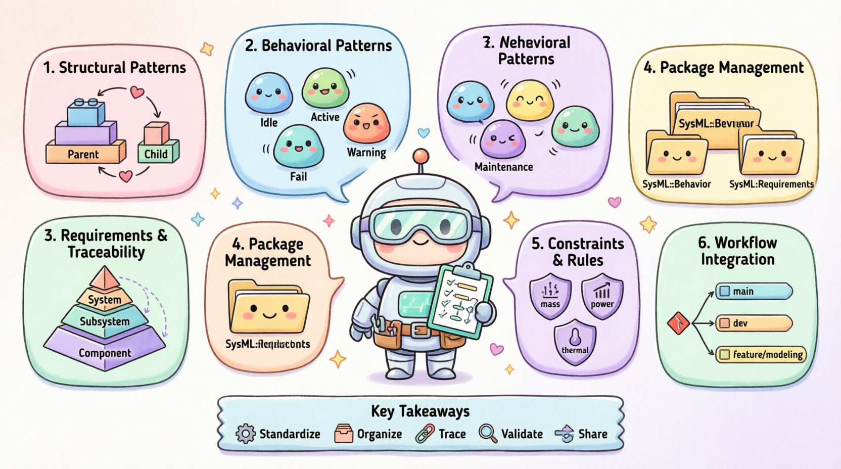
📝 Key Takeaways
Standardize: Use consistent patterns for structure, behavior, and requirements.
Organize: Use packages to manage model complexity.
Trace: Maintain clear links between requirements and design.
Validate: Use constraints to enforce system rules.
Share: Store patterns in a central repository for team use.
Adopting these practices will elevate the quality of systems engineering output. It creates a foundation upon which successful projects are built. Continue to refine your approach as you gain experience. The best patterns are those that evolve with your team.