Welcome to the foundational layer of software architecture modeling. When you move beyond simple class structures and need to visualize the internal workings of a classifier, the Composite Structure Diagram becomes your primary tool. This guide provides a deep dive into how to construct, interpret, and utilize these diagrams effectively within the Unified Modeling Language (UML) ecosystem.
Software architecture is not just about boxes and lines; it is about defining how components interact, what responsibilities they hold, and how they expose services to the outside world. A Composite Structure Diagram offers a specialized view that bridges the gap between high-level component diagrams and detailed class diagrams. It focuses on the internal structure of a classifier, revealing the parts, ports, and connections that make the system function.
Understanding the Core Purpose 🎯
Why choose a Composite Structure Diagram over other UML artifacts? The answer lies in granularity and interaction visibility. While a Class Diagram describes attributes and methods, and a Component Diagram describes deployable units, the Composite Structure Diagram focuses on the internal collaboration of a specific unit.
- Internal vs. External: It allows you to show the internal structure of a class or component without exposing the entire inheritance hierarchy.
- Interaction Focus: It highlights how parts communicate with each other via ports and connectors.
- Collaboration View: It demonstrates the roles parts play within the context of the whole.
This diagram type is particularly valuable when designing systems where encapsulation is critical, and you need to define how internal subsystems expose functionality to external clients or other internal parts.
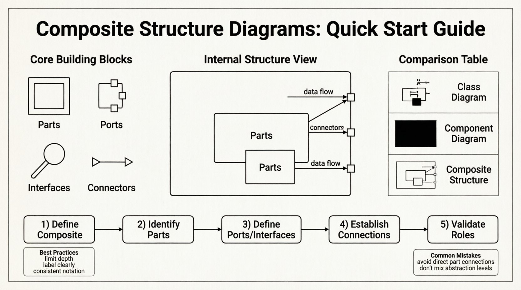
Core Building Blocks 🧩
To construct a valid Composite Structure Diagram, you must understand the specific semantics of its elements. Each element carries a distinct meaning regarding the flow of data and control within the system.
1. Parts and Instances
A Part represents a classifier that is contained within the composite structure. It is essentially an instance of a class or component that lives inside the main classifier.
- Role: Parts often play specific roles within the composite structure.
- Multiplicity: You can define how many instances of a part exist within a single composite (e.g., one to many).
- Visibility: Parts can be private, protected, or public, controlling access from outside the composite.
2. Ports
Ports are interaction points for parts. They act as the interface between the internal world and the external world. Without ports, a part cannot communicate with the outside.
- Provided Interfaces: Ports can provide services to other parts or the outside environment.
- Required Interfaces: Ports can request services from other parts or the outside environment.
- Encapsulation: Ports enforce encapsulation by restricting direct access to the internal state of a part.
3. Interfaces
An Interface defines a contract of operations. In a Composite Structure Diagram, interfaces are often attached to ports.
- Operation Definition: They specify what methods or signals can be exchanged.
- Implementation: A part implements an interface by providing the actual logic for the operations defined in the interface.
The Internal Structure View 🏗️
The heart of the Composite Structure Diagram is the Internal Structure compartment. This is where you define the composition of the classifier.
Defining the Classifier
The main box in the diagram represents the Composite Classifier. This could be a class, a component, or a node. It acts as the container for all internal elements.
Internal Compartments
Within the main classifier box, you will often see sections that delineate the internal parts. These are not just visual groupings; they define the logical decomposition of the system.
- Internal Parts: Boxes representing the classes that make up the composite.
- Internal Connections: Lines linking parts to each other or to the ports of the composite.
- Roles: Labels indicating the specific function a part serves in the connection.
Connectors and Communication Paths 🔌
Communication is the lifeblood of any software system. In this diagram, connectors define the paths along which information flows.
Types of Connectors
Connectors link ports to ports, or ports to parts. They establish the topology of the internal system.
- Association Connectors: Represent structural links between parts.
- Communication Paths: Indicate the flow of messages or data signals.
- Dependency Connectors: Show that one part relies on the functionality of another.
Roles and Multiplicity
Every connection has a role at each end. This defines the perspective of the connection.
- Source Role: The part initiating the interaction.
- Target Role: The part receiving the interaction.
- Multiplicity: Specifies how many instances can participate in the connection at one time.
Comparison with Other Diagrams 📊
Understanding where the Composite Structure Diagram fits in your modeling toolkit is essential for effective documentation.
| Diagram Type | Primary Focus | Internal Detail Level | Best Use Case |
|---|---|---|---|
| Class Diagram | Static structure, attributes, methods | High (but flat) | Defining data models and logic |
| Component Diagram | Physical deployable units | Low (Black box) | System deployment and physical structure |
| Composite Structure Diagram | Internal structure of a classifier | High (White box) | Defining internal collaboration and ports |
| Component Diagram | High-level architectural blocks | Medium | Macro-level system integration |
When you need to show how a specific class is built internally from other classes or components, the Composite Structure Diagram is superior to the standard Class Diagram. It allows you to abstract the internal complexity while maintaining the structural integrity of the design.
Constructing a Diagram: Logical Flow 🚀
Creating a Composite Structure Diagram requires a methodical approach. Follow these steps to ensure clarity and accuracy.
Step 1: Define the Composite
Start by identifying the main classifier you wish to decompose. This is your root node. What is the system or component you are analyzing? Is it a user session, a database connection pool, or a specific business logic module?
Step 2: Identify Internal Parts
List the classes or components that make up the internal logic of the composite. Ask yourself: “What smaller units are required to make this composite function?” These become the Parts within the diagram.
Step 3: Define Ports and Interfaces
For each part, determine how it interacts with the outside. Does it need to receive data? Does it need to send results? Create Ports and attach the necessary Interfaces (Provided or Required) to these ports.
Step 4: Establish Connections
Draw Connectors between the parts. Ensure that every required interface has a corresponding provided interface somewhere in the system. This creates a closed loop of functionality.
Step 5: Validate Roles
Review the connections. Does the role label accurately reflect the function of the part in that specific connection? For example, a “Reader” role is different from a “Writer” role, even if they use the same interface.
Best Practices for Clarity ✅
A complex diagram can become unreadable quickly. Adhere to these guidelines to maintain high quality.
- Limit Depth: Do not nest composite structures too deeply. If a part is complex, create a separate diagram for it rather than expanding the current one indefinitely.
- Use Groupings: Use compartments or frames to group related parts together logically.
- Label Interfaces Clearly: Ensure interface names describe the action (e.g., “ProcessRequest” rather than just “Interface1”).
- Consistent Notation: Stick to standard UML notation for ports (small squares) and connectors (lines).
- Focus on Collaboration: Only include elements that contribute to the interaction model. Remove static attributes that do not affect the structural flow.
Common Mistakes to Avoid 🚫
Even experienced modelers make errors when transitioning between diagram types. Be wary of these common pitfalls.
- Confusing Parts with Classes: Remember, a part is an instance within the composite structure, not just a class definition.
- Overlooking Ports: Do not connect parts directly to each other without using ports if you want to enforce encapsulation. Ports define the boundary.
- Mixing Levels of Abstraction: Do not mix high-level component views with low-level class attribute details in the same diagram.
- Ignoring Multiplicity: Failing to specify how many instances of a part are allowed can lead to ambiguity in implementation.
- Redundant Interfaces: Avoid defining interfaces that are identical to the part’s class interface unless there is a specific abstraction reason.
Real-World Application Scenarios 🌍
Where does this diagram add the most value in actual software development?
1. Microservices Architecture
In a microservices environment, you often need to define the internal structure of a service. A Composite Structure Diagram can show how the service is composed of handlers, validators, and adapters, all communicating through defined ports.
2. Embedded Systems
Hardware constraints require strict internal structuring. This diagram helps model how software modules map to hardware components, ensuring that ports align with physical I/O requirements.
3. Legacy Modernization
When refactoring legacy monoliths, you can use this diagram to map the internal structure of a module before breaking it apart. It helps identify which interfaces need to be exposed for external consumption.
4. Security Architecture
Security boundaries are often defined by interfaces. By modeling ports and their interfaces, you can explicitly show where authentication and authorization checks occur within the internal flow.
Deep Dive: Internal vs. External Views 🔍
The unique strength of this diagram is the ability to toggle between the internal and external views of a classifier.
The External View
From the outside, the composite appears as a single unit. It has a set of provided interfaces that other systems can use. The internal complexity is hidden behind this facade.
- Encapsulation: Internal parts are not directly accessible.
- Stability: Internal changes do not affect external clients as long as the interface contract remains the same.
The Internal View
Inside the composite, the structure is exposed. You can see how the provided interfaces are implemented by specific parts.
- Implementation: Shows which part handles which request.
- Flow: Shows how data moves from one internal part to another.
- Dependencies: Reveals internal coupling that might need optimization.
FAQ: Frequently Asked Questions ❓
Here are answers to common questions regarding the usage and interpretation of Composite Structure Diagrams.
Q: Is this diagram mandatory in UML?
No. It is an optional diagram type within UML 2.x. Use it when the internal structure adds necessary clarity that other diagrams cannot provide.
Q: Can I use this for hardware architecture?
Yes. While primarily for software, the concepts of parts, ports, and connectors apply to hardware components and their interconnections as well.
Q: How does this relate to Deployment Diagrams?
Deployment Diagrams show where software runs (nodes, devices). Composite Structure Diagrams show how the software itself is structured internally. They complement each other but serve different purposes.
Q: Can a part have its own internal structure?
Yes. A part can be a composite itself. This allows for recursive modeling, though care must be taken to avoid diagrams that become too deep to understand.
Q: What is the difference between a Component Diagram and a Composite Structure Diagram?
A Component Diagram typically shows the black-box view of components and their dependencies. A Composite Structure Diagram shows the white-box view of a specific classifier, detailing its internal composition.
Final Thoughts on Architecture Modeling 📝
Modeling software architecture is an exercise in abstraction and detail. The Composite Structure Diagram occupies a unique niche, offering the structural detail of a class diagram with the interaction focus of a component diagram. By understanding the roles of parts, ports, and connectors, you can create designs that are both robust and maintainable.
Focus on the flow of information and the boundaries of responsibility. When you model correctly, the resulting diagrams serve as blueprints that developers can follow to build systems that are flexible, secure, and scalable. Remember that a diagram is a communication tool; its primary goal is to convey intent clearly to stakeholders.
Start by applying these concepts to your next complex module. Define the parts, expose the ports, and map the connectors. You will find that the internal logic of your system becomes much clearer, leading to fewer bugs and better collaboration among your team.