Systems engineering relies heavily on clear communication to bridge the gap between abstract requirements and concrete implementation. At the heart of this communication lies the Systems Modeling Language (SysML). Among the various diagram types available, the Block Definition Diagram (BDD) serves as the structural backbone of a system model. Understanding how to read a BDD is not merely about recognizing symbols; it involves interpreting the logical architecture, relationships, and constraints that define a system’s behavior and composition.
This guide provides a structured approach to decoding Block Definition Diagrams. By breaking down the syntax and semantics into manageable components, you can analyze complex system structures with precision. Whether you are reviewing a design for a mechanical assembly or a software-defined system, the skills outlined here will help you navigate the model without ambiguity.
1. The Foundation: Understanding Blocks 🧱
The block is the fundamental unit of structure in SysML. When you open a BDD, the first task is to identify the blocks and understand their nature. A block represents a set of elements that share the same common properties and behaviors.
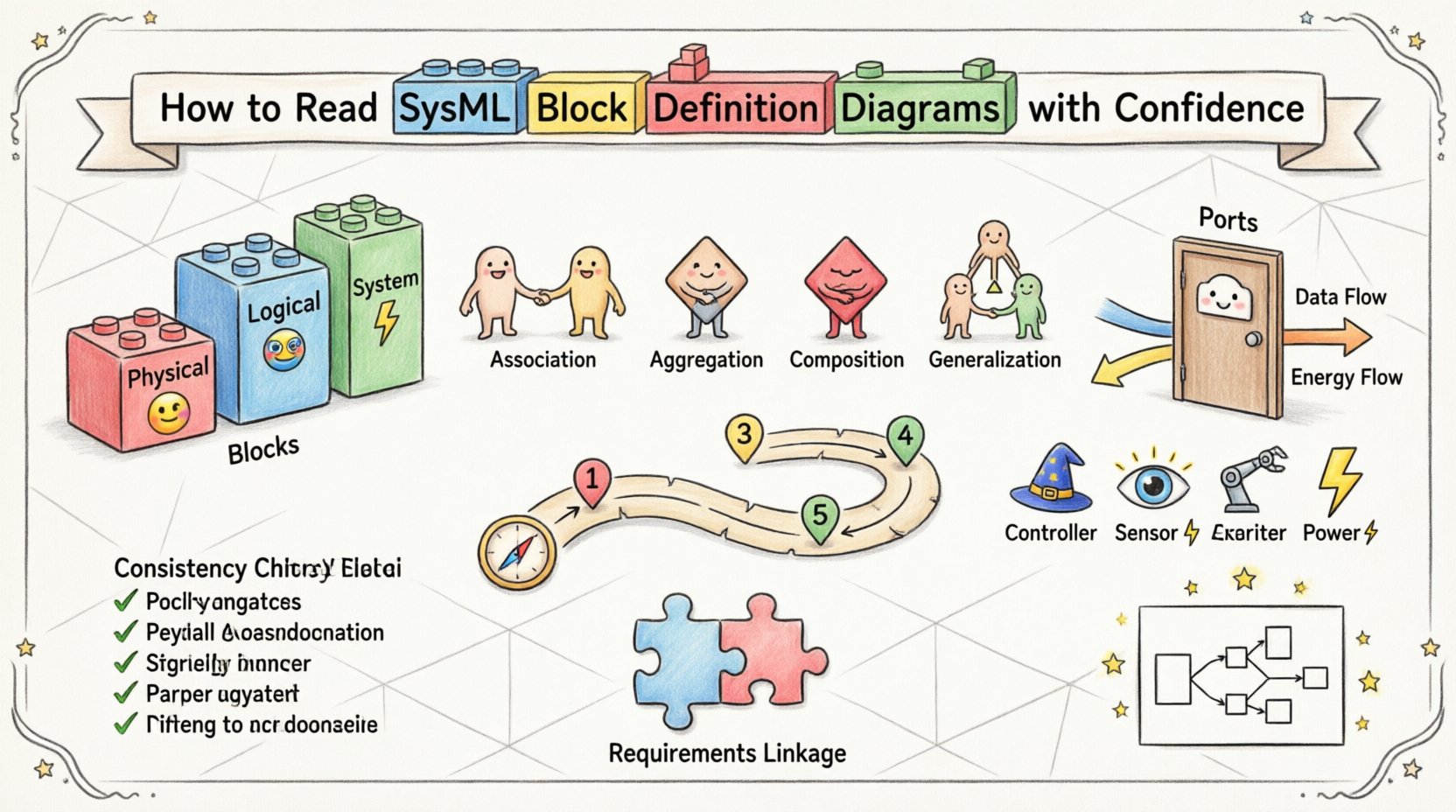
- Physical Blocks: These represent tangible items like sensors, actuators, or chassis components. They often have mass, volume, and material properties.
- Logical Blocks: These represent functions or software modules. They define what the system does rather than what it is made of.
- System Blocks: A system block encapsulates the entire scope of the project. It serves as the root node for the hierarchy.
When reading a diagram, look at the block shape. It is typically a rectangle with the block name in the header. Below the header, you will often see compartments. These compartments organize the internal details of the block.
Key Attributes to Check:
- Name: Ensure the name matches the requirement specification.
- Type: Is this a primitive type, a custom type, or a reference type?
- Constraints: Are there mathematical or logical constraints attached to the block?
2. Decoding Relationships 🔗
Relationships define how blocks interact with one another. In a BDD, you will encounter four primary types of relationships. Each carries a specific semantic meaning regarding ownership, dependency, or classification. Misinterpreting these lines can lead to significant errors in system design.
Association: This is the most basic connection. It indicates a link between two blocks where one can navigate to the other. It does not imply ownership. For example, a Driver block might be associated with a Vehicle block.
Aggregation: This represents a whole-part relationship where the part can exist independently of the whole. Think of a Team and Player. If the team dissolves, the players remain.
Composition: This is a stronger form of aggregation. The part cannot exist without the whole. If the whole is destroyed, the part is destroyed. A House is composed of Rooms. If the house is demolished, the rooms cease to exist in that context.
Generalization: This defines an inheritance relationship. It indicates that one block is a specialized version of another. A Truck is a type of Vehicle. This allows for the reuse of properties and operations.
To clarify the distinctions, refer to the comparison table below.
| Relationship Type | Symbol | Meaning | Lifecycle Dependency |
|---|---|---|---|
| Association | Solid Line | Connection between instances | None |
| Aggregation | Hollow Diamond | Whole-part, independent life | Part survives whole |
| Composition | Filled Diamond | Whole-part, dependent life | Part dies with whole |
| Generalization | Triangle Arrow | Inheritance (Is-a) | Specialized inherits parent |
3. Ports and Properties 🚪
Blocks are not isolated islands; they interact with their environment through ports and properties. Understanding the difference between these two is critical for reading interface definitions correctly.
Properties
A property is an internal feature of a block. It represents a component or a value that resides inside the block. When reading a property, consider the following:
- Reference Properties: Point to another block instance. They define structural composition.
- Value Properties: Hold primitive data like numbers, strings, or enumerated types. They define attributes like mass, speed, or color.
Ports
Ports define the interaction points between a block and the outside world. They are the gateways for flow or signal exchange.
- Standard Ports: Used for structural connections. They define how blocks are physically or logically connected.
- Flow Ports: Used for the exchange of value types. This is common for energy, fluids, or data streams.
When examining a port, look at the interface it uses. An interface defines the set of operations or flows that the port supports. This abstraction allows you to design the internal logic of a block without knowing exactly how it connects to the external system.
4. A Systematic Reading Approach 🧭
Reading a complex BDD can be overwhelming if you try to process everything at once. A systematic workflow helps maintain focus and ensures no detail is missed. Follow this sequence when analyzing a diagram.
- Step 1: Identify the Root Block. Locate the top-level system block. This sets the context for the entire model.
- Step 2: Trace the Hierarchy. Move down through the composition relationships. Map out the physical or logical decomposition.
- Step 3: Analyze Interfaces. Look at the ports and interfaces. Determine what data or energy crosses the boundaries of each block.
- Step 4: Review Constraints. Check for any constraints or parameters attached to blocks or relationships. These often contain critical performance metrics.
- Step 5: Cross-Reference. Verify that the blocks in the BDD align with the requirements model and the Activity Diagrams.
This workflow ensures that you understand the structure before diving into the behaviors. It prevents confusion between what a system is (structure) and what a system does (behavior).
5. Common Structural Patterns 📐
Experienced modelers tend to use recurring patterns to solve common system engineering problems. Recognizing these patterns can speed up your reading process significantly.
- The Controller Pattern: A block that manages other blocks. It often has interfaces for sending commands and receiving status updates.
- The Sensor Pattern: A block dedicated to measuring environmental variables. It typically connects via flow ports to a controller.
- The Actuator Pattern: A block that performs physical actions. It receives commands from a controller and executes them.
- The Power Bus Pattern: A block that distributes energy. It aggregates connections from power sources and distributes them to loads.
When you see a block acting as a central hub for multiple other blocks, suspect a controller pattern. If you see a block that only has input ports, it is likely a sensor. If it only has output ports, it is likely an actuator. These heuristics help you quickly infer the role of a block even without reading every attribute.
6. Ensuring Model Consistency ✅
A diagram is only useful if it is consistent with the rest of the model. Inconsistencies often arise when blocks are renamed in one diagram but not another, or when relationships are defined without proper typing.
Check for:
- Unique Identifiers: Ensure every block has a unique name within the package.
- Type Consistency: A property typed as Engine should always connect to a block of type Engine or a subtype.
- Directionality: Ensure flow ports respect the direction of the flow. A signal should not flow into a source.
- Documentation: Every block should have a description field populated. This text is vital for context when reading the model later.
Inconsistencies create ambiguity. If you are reading a BDD for a review, flag any property that lacks a type or any relationship that lacks a multiplicity. These gaps often indicate incomplete modeling work.
7. Linking Structure to Requirements 📝
The primary purpose of a BDD is to validate that the system structure satisfies the system requirements. You must be able to trace a requirement to a specific block or relationship.
When reading the diagram, ask these questions:
- Does the block hierarchy support the functional decomposition?
- Are there blocks missing that are required to meet a performance requirement?
- Do the interfaces defined in the ports match the interface requirements?
- Is the multiplicity on the relationships sufficient to meet the operational needs?
If a requirement states that the system must have redundancy, the BDD should show a composition or association pattern that reflects this redundancy. If the diagram shows a single path where redundancy is needed, the model is likely deficient.
8. Value Types and Reference Properties 💎
SysML distinguishes between value types and reference properties. This distinction is crucial for understanding data flow versus structural linkage.
- Reference Properties: These hold references to other blocks. They are used for structural composition. For example, a Car has a Wheel property.
- Value Properties: These hold data values. They are used for attributes like Mass or Temperature.
Confusion between these two can lead to modeling errors. A value property cannot have a relationship arrow pointing to another block. A reference property must point to a block definition. When reading a diagram, look at the data type. If it is a block name, it is a reference. If it is a number or string, it is a value.
9. Best Practices for Clarity 🌟
To make BDDs easier to read for others, follow these guidelines. These practices also help you when reading diagrams created by others.
- Keep Names Descriptive: Avoid single-letter names. Use PowerSupply instead of P.
- Use White Space: Arrange the diagram logically. Do not cluster all blocks in one corner.
- Group Related Blocks: Use internal partitions to group blocks that function together.
- Label Relationships: Always label the ends of association lines with multiplicity (e.g., 1..*, 0..1).
- Minimize Crossings: Try to route relationship lines so they do not cross unnecessarily. This reduces cognitive load.
When you encounter a messy diagram, it is often a sign that the modeling process was rushed. Look for the logical intent behind the visual chaos. Identify the root blocks and trace the composition chains to find the structure.
10. Integration with Other Diagrams 🔄
A BDD does not exist in isolation. It is part of a larger set of diagrams that describe the system. To fully understand a BDD, you often need to cross-reference other diagram types.
- Internal Block Diagram (IBD): Shows the internal wiring of a block. Use the IBD to see how ports connect.
- Parametric Diagram: Shows the constraints and equations. Use this to verify the value properties.
- Sequence Diagram: Shows the interaction over time. Use this to verify the flow ports.
For example, a BDD might show that a Motor is connected to a Wheel. The IBD will show the physical coupling mechanism. The Sequence Diagram will show the torque transmission over time. Reading the BDD in this context provides a complete picture of the system.
11. Troubleshooting Common Conflicts 🚧
Even with careful modeling, conflicts arise. Here are common issues you might encounter and how to interpret them.
Multiple Inheritance: SysML generally discourages multiple inheritance from blocks. If you see a block inheriting from two parents, check if this is intentional. It often indicates a design flaw.
Circular Dependencies: If Block A depends on Block B, and Block B depends on Block A, you have a circular dependency. This is usually a modeling error that prevents simulation or code generation.
Unresolved References: If a relationship points to a block that does not exist, the model is incomplete. Always verify that every referenced block is defined in the model.
12. Summary of Key Takeaways 📌
Reading SysML Block Definition Diagrams effectively requires a disciplined approach. You must understand the distinction between structure and behavior. You must recognize the specific meanings of relationships like composition and aggregation. You must verify that the ports and properties align with the interface requirements.
By following a systematic reading workflow, you can navigate complex models with ease. Focus on the hierarchy first, then the interfaces, and finally the constraints. Always cross-reference with other diagrams to ensure consistency.
Remember that the goal of the diagram is communication. A well-constructed BDD tells the story of the system clearly. Your ability to read it determines the quality of the engineering decisions you make based on that information.
Apply these principles to your own modeling work to create clearer, more maintainable diagrams. When you review others’ work, use this checklist to identify gaps or ambiguities. The result is a more robust system design and fewer errors during implementation.