Designing complex software systems requires more than just listing classes. You need to understand the internal anatomy of a component. This is where the Composite Structure Diagram becomes essential. It provides a detailed view of the internal structure of a classifier, showing how parts interact to achieve functionality. This guide walks you through the process of creating these diagrams without relying on specific tools.
Understanding the Composite Structure Diagram 🧩
A Composite Structure Diagram (CSD) represents the internal structure of a classifier. While a standard Class Diagram shows relationships between classes, a CSD focuses on the inside of a single class or component. It answers the question: What is inside this box?
- Decomposition: It breaks down a complex element into smaller, manageable parts.
- Collaboration: It shows how these parts work together to provide behavior.
- Interfaces: It defines how the internal parts communicate with the outside world.
This level of detail is crucial when designing systems with multiple layers, such as microservices, GUIs, or hardware-software integration. It helps architects visualize the boundaries and connections within a single unit.
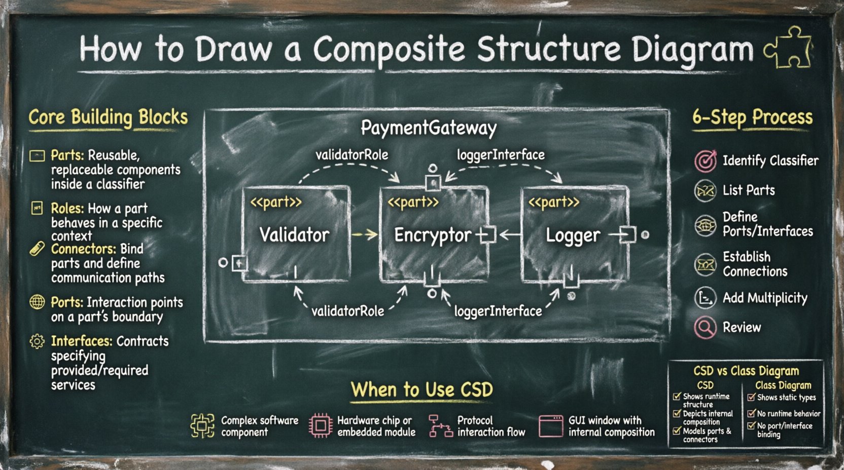
Core Building Blocks of the Diagram 🧱
To draw a Composite Structure Diagram effectively, you must understand its fundamental elements. Each element serves a specific purpose in defining the internal architecture.
1. Parts 🖥️
A Part represents an instance of a classifier within the composite structure. It is a specific piece of the system that contributes to the whole. In a diagram, a part is typically drawn as a rectangle with the stereotype <<part>> and the name of the instance below it.
- Instance vs. Type: A part is an instance, but it is typed by a class. You might have a
databaseConnectionpart typed by theConnectionclass. - Multiplicity: A part can have a multiplicity range, such as
1,0..1, or0..*, indicating how many instances exist.
2. Roles 🎭
A Role defines the capacity in which a part participates in a collaboration. A part might play different roles at different times or in different contexts.
- Context: Roles clarify the responsibility of the part within the structure.
- Labeling: Roles are often placed near the connector ends attached to the part.
3. Connectors 🔗
Connectors represent the physical or logical links between parts. They facilitate communication and data flow.
- Internal Links: Connectors link parts to other parts within the same composite structure.
- Binding: Connectors bind roles together, ensuring compatible interfaces interact correctly.
4. Ports 🌐
A Port is a distinct point of interaction between a component and its environment. It can be an input, output, or both.
- Encapsulation: Ports hide the internal details of the component from the outside.
- Interfaces: Ports realize specific interfaces, defining what services the part offers or requires.
5. Interfaces ⚙️
Interfaces define the contract for interaction. In a CSD, interfaces are often shown using lollipop notation (a circle) or interface boxes.
- Provided: The component offers this service (lollipop).
- Required: The component needs this service (socket).
When to Use a Composite Structure Diagram 📋
Not every class needs a CSD. Using them indiscriminately can clutter your documentation. Use this diagram when:
| Scenario | Reason |
|---|---|
| Complex Component | When a class has many internal dependencies. |
| Hardware Integration | When mapping software to physical devices. |
| Protocol Design | When defining internal communication flows. |
| GUI Layout | When showing how UI elements compose a window. |
Step-by-Step Process for Creation 🛠️
Creating a Composite Structure Diagram requires a methodical approach. Follow these steps to ensure accuracy and clarity.
Step 1: Identify the Target Classifier 🎯
Start with the class or component you want to analyze. This is your composite structure. Ensure you have a clear understanding of its overall responsibility.
Step 2: List Internal Parts 🧱
Break the classifier down. What sub-components make it work? List them out. For a Payment Gateway, parts might include Validator, Encryptor, and Logger.
- Draw a rectangle for the classifier.
- Add a compartment below the class name for the structure.
- Draw rectangles for each part inside this compartment.
Step 3: Define Interfaces and Ports 🌐
How does each part interact? Identify the interfaces each part provides or requires.
- Draw ports on the boundary of the parts.
- Attach interface symbols to the ports.
- Label the ports clearly (e.g.,
inputPort,outputPort).
Step 4: Establish Connections 🔗
Draw lines between the parts to show how they communicate. These lines are connectors.
- Ensure connectors link compatible roles.
- Use arrows to indicate direction if necessary.
- Label the connectors with the type of data or signal being passed.
Step 5: Specify Multiplicity and Constraints 📏
Add numbers to the ends of connectors to indicate how many instances are connected.
- Use
1for a single connection. - Use
0..*for optional or multiple connections. - Add notes if specific constraints exist (e.g.,
threadSafe).
Step 6: Review and Refine 🔍
Check the diagram for consistency. Ensure all parts are typed, all ports have interfaces, and the flow makes logical sense. Remove any redundant elements.
Deep Dive into Parts and Roles 👥
Understanding the nuance between a Part and a Role is critical for accurate modeling.
The Part: The Instance
A Part is the actual object residing within the structure. It is a concrete entity. When you instantiate a composite, you create instances of its parts.
- Example: In a
Carstructure, aEnginepart is a specific engine instance. - Labeling: Parts are often named in italics to distinguish them from class names.
The Role: The Capacity
A Role is the perspective from which the part is seen in a collaboration. A single part might play multiple roles in different contexts.
- Flexibility: Roles allow the same class to be reused in different structural configurations.
- Communication: Roles define the contract for the connection.
Consider a StorageDevice class. In one diagram, it might play the role of BackupTarget. In another, it might play the role of PrimaryVolume. The part remains the same, but the role changes.
Managing Ports and Connectors 🔌
Ports and connectors are the lifelines of the Composite Structure Diagram. They define the boundaries of encapsulation.
Internal vs. External Interaction
Internal connectors link parts to other parts. External connectors link parts to the outside world via the composite’s ports.
- Internal: These are hidden from the user of the composite.
- External: These are exposed through the composite’s own ports.
Interface Realization
Ports realize interfaces. This means a port is the physical point where the abstract interface is implemented.
- Provided Interface: The part offers a service through this port.
- Required Interface: The part consumes a service through this port.
Common Mistakes in Design ⚠️
Avoid these pitfalls to maintain the integrity of your diagrams.
- Over-Engineering: Do not create a CSD for every simple class. Only use it when internal complexity warrants it.
- Missing Interfaces: Ensure every port has an associated interface. Unconnected ports are ambiguous.
- Ignoring Multiplicity: Failing to specify how many parts exist can lead to runtime errors in implementation.
- Confusing Parts with Classes: Remember that parts are instances within the structure, not just class definitions.
- Unclear Roles: If a connector does not specify a role, it is unclear how the connection is interpreted.
Comparing CSD with Class Diagrams 📊
It is easy to confuse a Composite Structure Diagram with a Class Diagram. Here is how they differ.
| Feature | Class Diagram | Composite Structure Diagram |
|---|---|---|
| Focus | Relationships between classes. | Internal composition of a single class. |
| Granularity | High-level system view. | Low-level component view. |
| Elements | Attributes, Operations, Associations. | Parts, Ports, Connectors, Roles. |
| Usage | Database schema, API design. | System architecture, UI layout. |
Best Practices for Clarity ✨
Follow these guidelines to ensure your diagrams are readable and maintainable.
- Keep it Focused: One diagram should represent one specific classifier.
- Use Consistent Naming: Ensure part names and class names follow the same convention.
- Minimize Lines: Arrange parts to reduce the number of crossing lines.
- Group Related Parts: Use sub-structures or nested compartments if the diagram becomes too large.
- Document Constraints: Add notes for complex logic that cannot be shown visually.
Maintenance and Evolution 🔄
Software changes over time. A Composite Structure Diagram must evolve with the code.
- Version Control: Treat the diagram as code. Store it in your repository.
- Refactoring: If you refactor the internal structure, update the diagram immediately.
- Reviews: Include CSDs in architectural reviews to catch structural inconsistencies early.
- Automation: Where possible, generate diagrams from code to keep them in sync.
Final Considerations 🔍
Creating a Composite Structure Diagram is a disciplined exercise in decomposition. It forces you to think about the internal mechanics of your system rather than just the external behavior. By understanding parts, roles, ports, and connectors, you gain the ability to design systems that are modular, maintainable, and scalable.
Remember that diagrams are communication tools. Their primary goal is to convey information clearly to stakeholders, developers, and architects. Do not get lost in the details; focus on the structure that matters. With practice, drawing these diagrams will become a natural part of your design process.
Start with the simplest structures and gradually increase complexity. As you refine your skills, you will find that these diagrams provide a roadmap for implementation that is often more valuable than the code itself. They serve as the blueprint for the internal logic that drives your software.